Toyota Corolla Cross: Brake System Control Module "A" System Voltage System Voltage High (C137BA3)
DESCRIPTION
If a malfunction is detected in the power supply circuit, the skid control ECU (brake actuator assembly) stores this DTC and the fail-safe function prohibits ABS, brake assist, regenerative braking, etc. operation.
This DTC is stored when the +BS terminal voltage deviates due to a malfunction in a power supply or charging system circuit such as the auxiliary battery or DC/DC converter circuit, etc.
|
DTC No. |
Detection Item |
DTC Detection Condition |
Trouble Area |
MIL |
DTC Output from |
Note |
|---|---|---|---|---|---|---|
|
C137BA3 |
Brake System Control Module "A" System Voltage System Voltage High |
+BS terminal voltage is more than 16.5 V for 1 second or more. |
|
Comes on |
Brake/EPB |
|
MONITOR DESCRIPTION
When the supply voltage of the skid control ECU (brake actuator assembly) exceeds a certain value for a certain amount of time, the skid control ECU (brake actuator assembly) illuminates the MIL and stores this DTC.
MONITOR STRATEGY
|
Related DTCs |
C137D: Supply voltage monitoring (over voltage) |
|
Required Sensors/Components(Main) |
Skid control ECU (brake actuator assembly) |
|
Required Sensors/Components(Related) |
Skid control ECU (brake actuator assembly) |
|
Frequency of Operation |
Continuous |
|
Duration |
1 second |
|
MIL Operation |
2 driving cycles |
|
Sequence of Operation |
None |
TYPICAL ENABLING CONDITIONS
|
Monitor runs whenever the following DTCs are not stored |
TMC's intellectual property |
|
Other conditions belong to TMC's intellectual property |
- |
TYPICAL MALFUNCTION THRESHOLDS
|
TMC's intellectual property |
- |
COMPONENT OPERATING RANGE
|
TMC's intellectual property |
- |
CONFIRMATION DRIVING PATTERN
NOTICE:
When performing the normal judgment procedure, make sure that the driver door is closed and is not opened at any time during the procedure.
HINT:
- After repair has been completed, clear the DTC and then check that the vehicle has returned to normal by performing the following All Readiness check procedure.
- When clearing the permanent DTCs, refer to the "CLEAR PERMANENT DTC" procedure.
- Connect the GTS to the DLC3.
- Turn the ignition switch to ON and turn the GTS on.
- Clear the DTCs (even if no DTCs are stored, perform the clear DTC procedure).
- Turn the ignition switch off.
- Turn the ignition switch to ON (READY) and turn the GTS on.
- Wait for 1 second or more. [*]
HINT:
[*]: Normal judgment procedure.
The normal judgment procedure is used to complete DTC judgment and also used when clearing permanent DTCs.
- Enter the following menus: Chassis / Brake/EPB* / Utility / All Readiness.
*: Electric Parking Brake System
- Check the DTC judgment result.
HINT:
- If the judgment result shows NORMAL, the system is normal.
- If the judgment result shows ABNORMAL, the system has a malfunction.
- If the judgment result shows INCOMPLETE, perform driving pattern again.
WIRING DIAGRAM
Refer to DTC C117A49
Click here .gif)
CAUTION / NOTICE / HINT
NOTICE:
- Inspect the fuses for circuits related to this system before performing the following procedure.
- Before performing troubleshooting, make sure to confirm that the auxiliary
battery voltage is normal.
Click here
PROCEDURE
|
1. |
CHECK HARNESS AND CONNECTOR (+BS TERMINAL) |
|
(a) Make sure that there is no looseness at the locking part and the connecting part of the connector. OK: The connector is securely connected. |
|
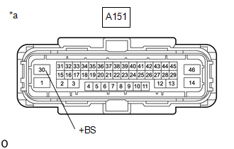
(b) Disconnect the A151 skid control ECU (brake actuator assembly) connector.
(c) Check both the connector case and the terminals for deformation and corrosion.
OK:
No deformation or corrosion.
(d) Measure the voltage according to the value(s) in the table below.
Standard Voltage:
|
Tester Connection |
Condition |
Specified Condition |
|---|---|---|
|
A151-30 (+BS) - Body ground |
Always |
11 to 14 V |
| OK | .gif)
|
REPLACE BRAKE ACTUATOR ASSEMBLY |
| NG |
|
REPAIR OR REPLACE HARNESS OR CONNECTOR |
READ NEXT:
 Stop Lamp Relay Actuator Stuck On (C13807E)
DESCRIPTION
When any of the following conditions are met, the skid control
ECU (brake actuator assembly) sets the drive output (STPO) ON which operates the
stop light control relay (stop light sw
Stop Lamp Relay Actuator Stuck Off (C13807F)
DESCRIPTION
Refer to DTC C13807E.
Click here
DTC No.
Detection Item
DTC Detection Condition
Trouble Area
MIL
DTC Output from
Electronic Brake Booster Motor "A" Current Sensor Circuit Voltage Out of Range
(C13BA1C)
DESCRIPTION
When the motor current sensor inside the electric brake booster
(brake booster with master cylinder assembly) meets the detection conditions, this
DTC is stored.
DTC No.
SEE MORE:
 Utility
UTILITY ALL READINESS
HINT:
With "All Readiness", you can check whether or not the DTC judgment has been completed by using the GTS.
Check "All Readiness" after simulating malfunction symptoms or for validation after finishing repairs.
(a) Clear the DTCs (even if no DTCs are s
Hybrid Transaxle Oil Seal
Components
COMPONENTS
ILLUSTRATION
*1
FRONT DRIVE SHAFT OIL SEAL LH
*2
FRONT DRIVE SHAFT OIL SEAL RH
●
Non-reusable part
-
-
Replacement
REPLACEMENT
CAUTION / NOTICE / HINT
The neces
