Toyota Corolla Cross: AT Solenoid Output Malfunction (P170300)
DESCRIPTION
The TCM controls the shift solenoid valves SL1, SL2 and SLG to change the shift mode from gear mode to belt mode and vice versa.
|
DTC No. |
Detection Item |
DTC Detection Condition |
Trouble Area |
MIL |
Memory |
Note |
|---|---|---|---|---|---|---|
|
P170300 |
AT Solenoid Output Malfunction |
Any of the following conditions are met for 1 second or more (2-trip detection logic):
|
|
Comes on |
DTC stored |
SAE Code: P1703 |
MONITOR DESCRIPTION
The TCM monitors the changes in the shift state from belt mode to gear mode for abnormalities.
If the vehicle is being driven in gear mode when in the belt mode vehicle speed range, the TCM detects a malfunction, illuminates the MIL and stores a DTC.
MONITOR STRATEGY
|
Related DTCs |
P1703: Incorrect shift solenoid performance/Functional check |
|
Required sensors/Components |
Transmission revolution sensor (NOUT) Shift solenoid valve SL1 Shift solenoid valve SL2 Shift solenoid valve SLG |
|
Frequency of operation |
Continuous |
|
Duration |
1 sec. |
|
MIL operation |
2 driving cycles |
|
Sequence of operation |
None |
TYPICAL ENABLING CONDITIONS
Condition (A)|
Output speed |
1200 rpm or more |
|
Time after following condition is met |
2 sec. or more |
|
- TCM indicate |
Belt mode |
|
Output speed |
2050 rpm or more |
TYPICAL MALFUNCTION THRESHOLDS
Condition (A) and (B)|
Shift solenoid valve SL1 |
ON |
|
Shift solenoid valve SL2 |
OFF |
|
Shift solenoid valve SLG |
ON |
CONFIRMATION DRIVING PATTERN
HINT:
- After repairs have been completed, clear the DTCs and then check that the vehicle has returned to normal by performing the following All Readiness check procedure.
- When clearing the permanent DTCs, refer to the Clear Permanent DTC procedure.
Click here
.gif)
- Clear the DTCs (even if no DTCs are stored, perform the clear DTC procedure).
- Turn the ignition switch off and wait for 2 minutes or more.
- Turn the ignition switch to ON and turn the GTS on.
- Start the engine.
- Perform the D Position Shift Test inspection in Road Test. [*1]
Click here
HINT:
[*1]: Normal judgment procedure.
The normal judgment procedure is used to complete DTC judgment and also used when clearing permanent DTCs.
- Enter the following menus: Powertrain / Transmission / Utility / All Readiness.
- Input the DTC: P170300.
- Check the DTC judgment result.
GTS Display
Description
NORMAL
- DTC judgment completed
- System normal
ABNORMAL
- DTC judgment completed
- System abnormal
INCOMPLETE
- DTC judgment not completed
- Perform driving pattern after confirming DTC enabling conditions
N/A
- Unable to perform DTC judgment
- Number of DTCs which do not fulfill DTC preconditions has reached ECU memory limit
HINT:
- If the judgment result shows NORMAL, the system is normal.
- If the judgment result shows ABNORMAL, the system has a malfunction.
- If the judgment result shows INCOMPLETE or N/A, perform the normal judgment procedure again.
WIRING DIAGRAM
Refer to DTC P074512, P077512 and P08C312.
for DTC P074512: Click here
for DTC P077512: Click here
for DTC P08C312: Click here
CAUTION / NOTICE / HINT
NOTICE:
- Perform the universal trip to clear permanent DTCs.
Click here
- Perform registration and/or initialization when parts related to the continuously
variable transaxle system are replaced.
Click here
- Check that no DTCs are stored after performing initialization.
Click here
PROCEDURE
|
1. |
CHECK DTC OUTPUT (IN ADDITION TO DTC P170300) |
(a) Enter the following menus:
Powertrain > Transmission > Trouble Codes(b) Read the DTCs using the GTS.
HINT:
If any DTCs other than P170300 are output, perform troubleshooting for those DTCs first.
|
Result |
Proceed to |
|---|---|
|
Only DTC P170300 is output |
A |
|
DTC P170300 and other DTCs are output |
B |
| B | .gif) |
GO TO DTC CHART |
|
.gif)
|
2. |
INSPECT CONTINUOUSLY VARIABLE TRANSAXLE ASSEMBLY (SHIFT SOLENOID VALVE SL1, SL2, SLG) |
|
(a) Disconnect the transmission wire connector. |
|
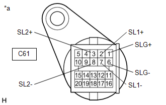
(b) Measure the resistance according to the value(s) in the table below.
Standard Resistance:
|
Tester Connection |
Condition |
Specified Condition |
|---|---|---|
|
2 (SL1+) - 7 (SL1-) |
20°C (68°F) |
5.0 to 5.6 Ω |
|
3 (SL2+) - 8 (SL2-) |
20°C (68°F) |
5.0 to 5.6 Ω |
|
1 (SLG+) - 6 (SLG-) |
20°C (68°F) |
5.0 to 5.6 Ω |
|
2 (SL1+) or 7 (SL1-) - Body ground and other terminals |
Always |
10 kΩ or higher |
|
3 (SL2+) or 8 (SL2-) - Body ground and other terminals |
Always |
10 kΩ or higher |
|
1 (SLG+) or 6 (SLG-) - Body ground and other terminals |
Always |
10 kΩ or higher |
(c) Connect the transmission wire connector.
| NG | |
GO TO STEP 5 |
|
|
3. |
CHECK HARNESS AND CONNECTOR (TRANSMISSION WIRE - TCM) |
(a) Disconnect the C80 TCM connector.
(b) Measure the resistance according to the value(s) in the table below.
Standard Resistance:
|
Tester Connection |
Condition |
Specified Condition |
|---|---|---|
|
C80-38 (SL1+) - C80-37 (SL1-) |
20°C (68°F) |
5.0 to 5.6 Ω |
|
C80-19 (SL2+) - C80-20 (SL2-) |
20°C (68°F) |
5.0 to 5.6 Ω |
|
C80-21 (SLG+) - C80-22 (SLG-) |
20°C (68°F) |
5.0 to 5.6 Ω |
|
C80-38 (SL1+) or C80-37 (SL1-) - Body ground and other terminals |
Always |
10 kΩ or higher |
|
C80-19 (SL2+) or C80-20 (SL2-) - Body ground and other terminals |
Always |
10 kΩ or higher |
|
C80-21 (SLG+) or C80-22 (SLG-) - Body ground and other terminals |
Always |
10 kΩ or higher |
(c) Connect the C80 TCM connector.
| NG | |
REPAIR OR REPLACE HARNESS OR CONNECTOR (TRANSMISSION WIRE - TCM) |
|
|
4. |
REPLACE TCM |
Click here
| NEXT | |
PERFORM REGISTRATION AND INITIALIZATION for Registration: Click here for Initialization: Click here |
|
5. |
INSPECT TRANSMISSION VALVE BODY ASSEMBLY (SHIFT SOLENOID VALVE SL1, SL2 AND SLG) |
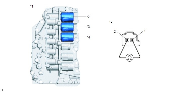
(a) Disconnect the transmission wire connector from the shift solenoid valves SL1, SL2 and SLG.
Click here
|
*1 |
Transmission Valve Body Assembly |
*2 |
Shift Solenoid Valve SLG |
|
*3 |
Shift Solenoid Valve SL1 |
*4 |
Shift Solenoid Valve SL2 |
|
*a |
Component without harness connected (Shift Solenoid Valve SL1, SL2 and SLG) |
- |
- |
(b) Measure the resistance according to the value(s) in the table below.
Standard Resistance:
|
Tester Connection |
Condition |
Specified Condition |
|---|---|---|
|
Shift solenoid valve SL1 connector terminal 1 - terminal 2 |
20°C (68°F) |
5.0 to 5.6 Ω |
|
Shift solenoid valve SL2 connector terminal 1 - terminal 2 |
20°C (68°F) |
5.0 to 5.6 Ω |
|
Shift solenoid valve SLG connector terminal 1 - terminal 2 |
20°C (68°F) |
5.0 to 5.6 Ω |
| OK | |
REPLACE TRANSMISSION WIRE |
|
|
6. |
REPLACE CONTINUOUSLY VARIABLE TRANSAXLE ASSEMBLY |
Click here
| NEXT | |
PERFORM REGISTRATION AND INITIALIZATION for Registration: Click here for Initialization: Click here |


