Toyota Corolla Cross: Antenna Coil Circuit Voltage Out of Range (B27841C)
DESCRIPTION
When an open or short circuit is detected in the transponder key amplifier coil built into the engine switch, the certification ECU (smart key ECU assembly) stores this DTC. This DTC is also stored as a history DTC.
|
DTC No. | Detection Item |
DTC Detection Condition | Trouble Area |
Note |
|---|---|---|---|---|
| B27841C |
Antenna Coil Circuit Voltage Out of Range |
The transponder key amplifier coil built into the engine switch is open (see below) or shorted (determined by communication with certification ECU (smart key ECU assembly)). (1 trip detection logic*) |
| DTC output confirmation operation:
|
- *: Only output while a malfunction is present.
|
Vehicle Condition when Malfunction Detected |
Fail-safe Operation when Malfunction Detected |
|---|---|
|
Engine cannot be started when transmitter battery is depleted by holding electrical key transmitter sub-assembly near engine switch and pressing and holding engine switch with shift lever in P |
- |
|
DTC No. | Data List and Active Test |
|---|---|
|
B27841C | - |
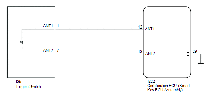
WIRING DIAGRAM
CAUTION / NOTICE / HINT
NOTICE:
- When using the GTS with the ignition switch off, connect the GTS to the DLC3 and turn a courtesy light switch on and off at intervals of 1.5 seconds or less until communication between the GTS and the vehicle begins. Then select the vehicle type under manual mode and enter the following menus: Body Electrical / Smart Key. While using the GTS, periodically turn a courtesy light switch on and off at intervals of 1.5 seconds or less to maintain communication between the GTS and the vehicle.
- The smart key system (for Start Function) uses the LIN communication system and CAN communication system. Inspect the communication function by following How to Proceed with Troubleshooting. Troubleshoot the smart key system (for Start Function) after confirming that the communication systems are functioning properly.
Click here
.gif)
- Before replacing the certification ECU (smart key ECU assembly), refer to Registration.
Click here
- After performing repairs, confirm that no DTCs are output by performing "DTC Output Confirmation Operation".
PROCEDURE
|
1. | CHECK CONNECTION OF CONNECTOR |
(a) Check that the connectors are properly connected to the engine switch and certification ECU (smart key ECU assembly).
OK:
Connectors are properly connected.
| NG | .gif) | CONNECT CONNECTORS PROPERLY |
|
.gif)
| 2. |
CHECK HARNESS AND CONNECTOR (CERTIFICATION ECU (SMART KEY ECU ASSEMBLY) - ENGINE SWITCH AND BODY GROUND) |
(a) Disconnect the I222 certification ECU (smart key ECU assembly) connector.
(b) Disconnect the I35 engine switch connector.
(c) Measure the resistance according to the value(s) in the table below.
Standard Resistance:
|
Tester Connection | Condition |
Specified Condition |
|---|---|---|
|
I222-12 (ANT1) - I35-1 (ANT1) |
Always | Below 1 Ω |
|
I222-12 (ANT1) or I35-1 (ANT1) - Body ground |
Always | 10 kΩ or higher |
|
I222-13 (ANT2) - I35-7 (ANT2) |
Always | Below 1 Ω |
|
I222-13 (ANT2) or I35-7 (ANT2) - Body ground |
Always | 10 kΩ or higher |
| NG | | REPAIR OR REPLACE HARNESS OR CONNECTOR |
|
| 3. |
CHECK CERTIFICATION ECU (SMART KEY ECU ASSEMBLY) |
(a) Connect the I222 certification ECU (smart key ECU assembly) connector.
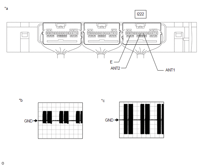
(b) Using an oscilloscope, check the waveform.
|
*a | Component with harness connected (Certification ECU (Smart Key ECU Assembly)) |
*b | Waveform 1 |
|
*c | Waveform 2 |
- | - |
OK:
|
Tester Connection | Condition |
Tool Setting | Specified Condition |
|---|---|---|---|
|
I222-12 (ANT1) - I222-29 (E) |
Ignition switch off, electrical key transmitter sub-assembly not in cabin, within 30 seconds of engine switch pressed |
2 V/DIV., 500 ms./DIV. |
Pulse generation (See waveform 1) |
|
I222-13 (ANT2) - I222-29 (E) |
Ignition switch off, electrical key transmitter sub-assembly not in cabin, within 30 seconds of engine switch pressed |
2 V/DIV., 500 ms./DIV. |
Pulse generation (See waveform 2) |
| OK | | REPLACE ENGINE SWITCH |
| NG | | REPLACE CERTIFICATION ECU (SMART KEY ECU ASSEMBLY) |
READ NEXT:
 ID-BOX Component Internal Failure (B278D96)
DESCRIPTION When the certification ECU (smart key ECU assembly) detects an input signal indicating that the vehicle is equipped with an ID code box even though the ID code box is not registered, the c
Immobiliser Amp Missing Message (B278E87)
DESCRIPTION A transponder key amplifier is built into the certification ECU (smart key ECU assembly).
When a communication malfunction occurs with the transponder key amplifier inside the certificat
ID-BOX Calibration / Parameter Memory Failure (B279046)
DESCRIPTION When an internal malfunction occurs in the ID code box (immobiliser code ECU), the certification ECU (smart key ECU assembly) stores this DTC.
DTC No. Detection Item
DTC Detec
SEE MORE:
 PKSB (Parking Support Brake)
The PKSB (Parking Support
Brake) consists of the following
functions that operate
when driving at a low
speed or backing up, such
as when parking. When the
system determines that the
possibility of a collision
with a detected object is
high, a warning operates to
urge the driver to take evasive
acti
Removal
REMOVAL
CAUTION / NOTICE / HINT
COMPONENTS (REMOVAL)
Procedure
Part Name Code
1
ECM
89661
-
-
-
2
AUXILIARY BATTERY
-
-
