Toyota Corolla Cross: "A" Camshaft Position Actuator Bank 1 General Electrical Failure (P136001)
DESCRIPTION
Refer to DTC P001001.
Click here
.gif)
|
DTC No. | Detection Item |
DTC Detection Condition | Trouble Area |
MIL | Note |
|---|---|---|---|---|---|
|
P136001 | "A" Camshaft Position Actuator Bank 1 General Electrical Failure |
While engine is running, malfunction in rotation signal (VTS) of cam timing control motor with EDU assembly is detected for 3 seconds (1 trip detection logic). |
| Comes on |
|
|
Vehicle Condition | Fail-Safe |
|---|---|
| The cam timing control motor with EDU assembly is operated to the most retarded position. |
MONITOR DESCRIPTION
This DTC is output when a rotation signal malfunction is detected in the cam timing control motor with EDU assembly. While the engine is running, if a rotation signal (VTS) malfunction is detected, a DTC is immediately output (1 trip detection logic).
MONITOR STRATEGY
|
Related DTCs | P1360: Camshaft position signal range check |
|
Required sensors/Components (Main) | Cam timing control motor with EDU assembly |
|
Required sensors/Components (Related) |
- |
| Frequency of Operation |
Continuous |
| Duration |
3 seconds |
| MIL Operation |
Immediate |
| Sequence of Operation |
None |
TYPICAL ENABLING CONDITIONS
|
Monitor runs whenever the following DTCs are not stored |
None |
| All of the following conditions are met |
- |
| Auxiliary battery voltage |
11 V or higher |
| Ignition switch |
ON |
| Engine speed |
100 rpm or higher |
| VVT motor direction calculated by camshaft position deviation |
Forward |
TYPICAL MALFUNCTION THRESHOLDS
|
VVT motor speed at VVT revolution sensor |
0 rpm or less |
CONFIRMATION DRIVING PATTERN
HINT:
- After repair has been completed, clear the DTC and then check that the vehicle has returned to normal by performing the following All Readiness check procedure.
Click here
- When clearing the permanent DTCs, refer to the "CLEAR PERMANENT DTC" procedure.
Click here
- Connect the GTS to the DLC3.
- Turn the ignition switch to ON.
- Turn the GTS on.
- Clear the DTCs (even if no DTCs are stored, perform the clear DTC procedure).
- Turn the ignition switch off and wait for at least 30 seconds.
- Start the engine [A].
- Idle the engine for 30 seconds or more [B].
- Turn the GTS on.
- Enter the following menus: Powertrain / Engine / Trouble Codes [C].
- Read pending the DTCs.
HINT:
- If a pending DTC is output, the system is malfunctioning.
- If a pending DTC is not output, perform the following procedure.
- Enter the following menus: Powertrain / Engine / Utility / All Readiness.
- Input the DTC: P136001.
- Check the DTC judgment result.
GTS Display
Description
NORMAL
- DTC judgment completed
- System normal
ABNORMAL
- DTC judgment completed
- System abnormal
INCOMPLETE
- DTC judgment not completed
- Perform driving pattern after confirming DTC enabling conditions
HINT:
- If the judgment result is NORMAL, the system is normal.
- If the judgment result is ABNORMAL, the system has a malfunction.
- If the judgment result is INCOMPLETE, perform steps [A] through [C] again.
- [A] to [C]: Normal judgment procedure.
The normal judgment procedure is used to complete DTC judgment and also used when clearing permanent DTCs.
- When clearing the permanent DTCs, do not disconnect the cable from the auxiliary battery terminal or attempt to clear the DTCs during this procedure, as doing so will clear the universal trip and normal judgment histories.
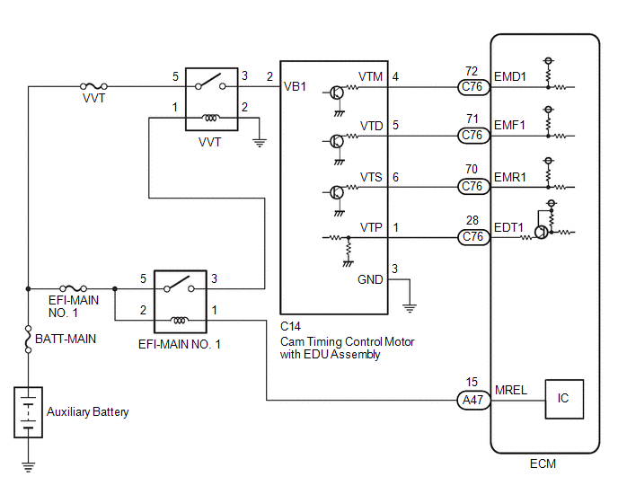
WIRING DIAGRAM
CAUTION / NOTICE / HINT
NOTICE:
Inspect the fuses for circuits related to this system before performing the following procedure.
HINT:
Read Freeze Frame Data using the GTS. The ECM records vehicle and driving condition information as Freeze Frame Data the moment a DTC is stored. When troubleshooting, Freeze Frame Data can help determine if the vehicle was moving or stationary, if the engine was warmed up or not, if the air fuel ratio was lean or rich, and other data from the time the malfunction occurred.
PROCEDURE
| 1. |
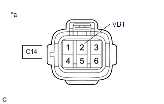
CHECK TERMINAL VOLTAGE (POWER SOURCE OF CAM TIMING CONTROL MOTOR WITH EDU ASSEMBLY) |
| (a) Disconnect the cam timing control motor with EDU assembly connector. |
|
(b) Turn the ignition switch to ON.
(c) Measure the voltage according to the value(s) in the table below.
Standard Voltage:
|
Tester Connection | Condition |
Specified Condition |
|---|---|---|
|
C14-2 (VB1) - Body ground |
Ignition switch ON | 11 to 14 V |
| NG | .gif) | GO TO STEP 8 |
|
.gif)
| 2. |
CHECK HARNESS AND CONNECTOR (CAM TIMING CONTROL MOTOR WITH EDU ASSEMBLY - BODY GROUND) |
(a) Disconnect the cam timing control motor with EDU assembly connector.
(b) Measure the resistance according to the value(s) in the table below.
Standard Resistance:
|
Tester Connection | Condition |
Specified Condition |
|---|---|---|
|
C14-3 (GND) - Body ground |
Always | Below 1 Ω |
| NG | | REPAIR OR REPLACE HARNESS OR CONNECTOR |
|
| 3. |
INSPECT CAM TIMING CONTROL MOTOR WITH EDU ASSEMBLY (BODY GROUND) |
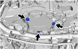
(a) Check installation condition.
- Check that the 3 installation bolts of the cam timing control motor with EDU assembly are tightened to the specified torque.
Torque:
21 N*m (214 kgf*cm, 15 ft.*lbf)
| NG | | TIGHTEN TO SPECIFIED TORQUE |
|
| 4. |
CHECK HARNESS AND CONNECTOR (CAM TIMING CONTROL MOTOR WITH EDU ASSEMBLY - ECM) |
(a) Disconnect the cam timing control motor with EDU assembly connector.
(b) Disconnect the ECM connector.
(c) Measure the resistance according to the value(s) in the table below.
Standard Resistance:
|
Tester Connection | Condition |
Specified Condition |
|---|---|---|
|
C14-6 (VTS) - C76-70 (EMR1) |
Always | Below 1 Ω |
|
C14-6 (VTS) or C76-70 (EMR1) - Body ground and other terminals |
Always | 10 kΩ or higher |
| NG | | REPAIR OR REPLACE HARNESS OR CONNECTOR |
|
| 5. |
REPLACE CAM TIMING CONTROL MOTOR WITH EDU ASSEMBLY |
Click here
HINT:
Perform "Inspection After Repair" after replacing the cam timing control motor with EDU assembly.
Click here
|
| 6. |
CLEAR DTC |
(a) Clear the DTCs.
Powertrain > Engine > Clear DTCs(b) Turn the ignition switch off and wait for at least 30 seconds.
|
| 7. |
CONFIRM WHETHER MALFUNCTION HAS BEEN SUCCESSFULLY REPAIRED |
(a) Drive the vehicle in accordance with the driving pattern described in Confirmation Driving Pattern.
(b) Read the DTCs.
Powertrain > Engine > Trouble Codes|
Result | Proceed to |
|---|---|
|
DTCs are not output | A |
|
DTC P136001 is output |
B |
| A |
| END |
| B |
| REPLACE ECM
|
| 8. |
INSPECT VVT RELAY |
Click here
| NG | |
REPLACE VVT RELAY |
|
| 9. |
CHECK HARNESS AND CONNECTOR (VVT RELAY - CAM TIMING CONTROL MOTOR WITH EDU ASSEMBLY) |
(a) Remove the VVT relay from No. 1 engine room relay block assembly.
(b) Disconnect the cam timing control motor with EDU assembly connector.
(c) Measure the resistance according to the value(s) in the table below.
Standard Resistance:
|
Tester Connection | Condition |
Specified Condition |
|---|---|---|
|
3 (VVT relay) - C14-2 (VB1) |
Always | Below 1 Ω |
|
3 (VVT relay) or C14-2 (VB1) - Body ground and other terminals |
Always | 10 kΩ or higher |
| NG | | REPAIR OR REPLACE HARNESS OR CONNECTOR |
|
| 10. |
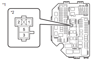
CHECK HARNESS AND CONNECTOR (POWER SOURCE OF VVT RELAY) |
|
*1 | No. 1 Engine Room Relay Block Assembly |
|
*2 | VVT Relay |
(a) Remove the VVT relay from No. 1 engine room relay block assembly.
(b) Measure the voltage according to the value(s) in the table below.
Standard Voltage:
|
Tester Connection | Condition |
Specified Condition |
|---|---|---|
|
5 (VVT relay) - Body ground |
Always | 11 to 14 V |
| NG | | REPAIR OR REPLACE HARNESS OR CONNECTOR (AUXILIARY BATTERY - VVT RELAY) |
|
| 11. |
CHECK HARNESS AND CONNECTOR (POWER SOURCE OF VVT RELAY) |
|
*1 | No. 1 Engine Room Relay Block Assembly |
|
*2 | VVT Relay |
(a) Remove the VVT relay from No. 1 engine room relay block assembly.
(b) Turn the ignition switch to ON.
(c) Measure the voltage according to the value(s) in the table below.
Standard Voltage:
|
Tester Connection | Condition |
Specified Condition |
|---|---|---|
|
1 (VVT relay) - Body ground |
Ignition switch ON | 11 to 14 V |
| OK | | REPAIR OR REPLACE HARNESS OR CONNECTOR (VVT RELAY - BODY GROUND) |
| NG | | REPAIR OR REPLACE HARNESS OR CONNECTOR (EFI-MAIN NO. 1 RELAY - VVT RELAY) |


