Toyota Corolla Cross: Terminals Of Ecu
TERMINALS OF ECU
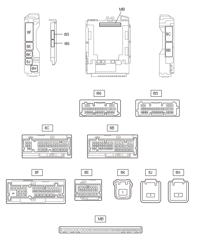
CHECK MAIN BODY ECU (MULTIPLEX NETWORK BODY ECU) AND POWER DISTRIBUTION BOX ASSEMBLY
(a) Remove the main body ECU (multiplex network body ECU) from the power distribution box assembly.
Click here .gif)
(b) Reconnect the power distribution box assembly connectors.
(c) Measure the resistance and voltage according to the value(s) in the table below.
|
Terminal No. (Symbol) | Terminal Description |
Condition | Specified Condition |
|---|---|---|---|
|
MB-26 (BECU) - Body ground |
Auxiliary battery power supply |
Ignition switch off | 11 to 14 V |
|
MB-27 (IGR) - Body ground |
Ignition power supply (IG signal) |
Ignition switch off | Below 1 V |
|
Ignition switch ON | 11 to 14 V | ||
|
MB-13 (GND1) - Body ground |
Ground | Always |
Below 1 Ω |
|
MB-14 (GND2) - Body ground |
Ground | Always |
Below 1 Ω |
|
MB-2 (FLCY) - Body ground |
Front door courtesy light switch assembly (LH) input |
Front door LH closed |
10 kΩ or higher |
|
Front door LH open | Below 1 Ω | ||
|
MB-4 (FRCY) - Body ground |
Front door courtesy light switch assembly (RH) input |
Front door RH closed |
10 kΩ or higher |
|
Front door RH open | Below 1 Ω | ||
|
MB-6 (LCTY) - Body ground |
Rear door courtesy light switch assembly (LH) input |
Rear door LH closed | 10 kΩ or higher |
|
Rear door LH open | Below 1 Ω | ||
|
MB-1 (RCTY) - Body ground |
Rear door courtesy light switch assembly (RH) input |
Rear door RH closed | 10 kΩ or higher |
|
Rear door RH open | Below 1 Ω | ||
|
I85-27 (HCTY) - Body ground |
Engine hood courtesy switch input |
Engine hood open | 10 kΩ or higher |
|
Engine hood closed | Below 1 Ω | ||
|
8F-2 (BCTY) - Body ground |
Back door courtesy light switch input |
Back door closed | 10 kΩ or higher |
|
Back door open | Below 1 Ω |
(d) Install the main body ECU (multiplex network body ECU) to power distribution box assembly.
Click here
(e) Measure the voltage and check for pulses according to the value(s) in the table below.
|
Terminal No. (Symbol) | Terminal Description |
Condition | Specified Condition |
|---|---|---|---|
|
I85-9 (LSFL) - Body ground |
Front door LH unlock detection switch input |
Front door LH unlocked |
Below 1 V |
|
Front door LH locked |
Pulse generation | ||
|
I85-3 (LSFR) - Body ground |
Front door RH unlock detection switch input |
Front door RH unlocked |
Below 1 V |
|
Front door RH locked |
Pulse generation | ||
|
I85-10 (LSWL) - Body ground |
Rear door LH unlock detection switch input |
Rear door LH unlocked |
Below 1 V |
|
Rear door LH locked | Pulse generation | ||
|
I86-23 (LSWR) - Body ground |
Rear door RH unlock detection switch input |
Rear door RH unlocked |
Below 1 V |
|
Rear door RH locked | Pulse generation | ||
|
I85-28 (L2) - Body ground |
Driver door key-linked lock input |
Driver door key cylinder turned to lock position |
Below 1 V |
|
Driver door key cylinder off |
Pulse generation | ||
|
I85-4 (UL3) - Body ground |
Driver door key-linked unlock input |
Driver door key cylinder turned to unlock position |
Below 1 V |
|
Driver door key cylinder off |
Pulse generation | ||
|
8E-4 (SH) - Body ground |
Security horn assembly drive |
Security horn assembly sounding (Theft deterrent system in alarm sounding state) |
Pulse generation (Below 1 V ← → 11 to 14 V) |
|
8E-11 (HORN) - Body ground |
Vehicle horns drive | Vehicle horns sounding (Theft deterrent system in alarm sounding state) |
Pulse generation (Below 1 V ← → 11 to 14 V) |


