Toyota Corolla Cross: Terminals Of Ecu
TERMINALS OF ECU
CHECK POWER DISTRIBUTION BOX ASSEMBLY AND MAIN BODY ECU (MULTIPLEX NETWORK BODY ECU)
.png)
(a) Remove the main body ECU (multiplex network body ECU) from the power distribution box assembly.
(b) Reconnect the power distribution box assembly connectors.
(c) Measure the voltage and resistance according to the value(s) in the table below.
HINT:
Measure the values on the wire harness side with the connectors connected.
|
Terminal No. (Symbol) | Terminal Description |
Condition | Specified Condition |
|---|---|---|---|
|
MB-13 (GND1) - Body ground |
Ground | Always |
Below 1 Ω |
|
MB-14 (GND2) - Body ground |
Ground | Always |
Below 1 Ω |
|
MB-26 (BECU) - Body ground |
Auxiliary battery power supply |
Ignition switch off | 11 to 14 V |
|
MB-27 (IGR) - Body ground |
IG power supply | Ignition switch ON |
11 to 14 V |
(d) Install the main body ECU (multiplex network body ECU) to the power distribution box assembly.
(e) Measure the voltage and check for pulses according to the value(s) in the table below.
|
Terminal No. (Symbol) | Terminal Description |
Condition | Specified Condition |
|---|---|---|---|
|
8F-5 (FRCY) - Body ground |
Front door courtesy light switch (for RH) input |
Front door RH open | Below 1 V |
|
Front door RH closed |
11 to 14 V | ||
|
8F-3 (FLCY) - Body ground |
Front door courtesy light switch (for LH) input |
Front door LH open | Below 1 V |
|
Front door LH closed |
11 to 14 V | ||
|
8F-1 (RCTY) - Body ground |
Rear door courtesy light switch (for RH) input |
Rear door RH open | Below 1 V |
|
Rear door RH closed | Pulse generation | ||
|
8F-28 (LCTY) - Body ground |
Rear door courtesy light switch (for LH) input |
Rear door LH open | Below 1 V |
|
Rear door LH closed | Pulse generation | ||
|
8F-2 (BCTY) - Body ground |
Back door courtesy light switch input |
Back door closed | Below 1 V |
|
Back door open | 11 to 14 V | ||
|
8F-42 (TR+) - Body ground |
Back door lock motor drive output |
Back door closed → open |
Below 1 V → 11 to 14 V → Below 1 V |
|
8F-36 (ACT-) - Body ground |
Door lock motor unlock drive output |
Door control switch or driver door key cylinder off → on (unlock) |
Below 1 V → 11 to 14 V → Below 1 V |
|
8F-37 (ACT-) - Body ground | |||
|
8F-40 (ACT+) - Body ground |
Door lock motor lock drive output |
Door control switch or driver door key cylinder off → on (lock) |
Below 1 V → 11 to 14 V → Below 1 V |
|
8F-41 (ACT+) - Body ground | |||
|
I85-3 (LSFR) - Body ground |
Front door RH unlock detection switch input |
Front door RH unlocked |
Below 1 V |
|
Front door RH locked |
Pulse generation | ||
|
I85-9 (LSFL) - Body ground |
Front door LH unlock detection switch input |
Front door LH unlocked |
Below 1 V |
|
Front door LH locked |
Pulse generation | ||
|
I86-23 (LSWR) - Body ground |
Rear door RH unlock detection switch input |
Rear door RH unlocked |
Below 1 V |
|
Rear door RH locked | Pulse generation | ||
|
I85-10 (LSWL) - Body ground |
Rear door LH unlock detection switch input |
Rear door LH unlocked |
Below 1 V |
|
Rear door LH locked | Pulse generation | ||
|
I85-28 (L2) - Body ground |
Driver door key-linked lock input |
Driver door key cylinder turned to lock |
Below 1 V |
|
Driver door key cylinder not turned |
Pulse generation | ||
|
I85-4 (UL3) - Body ground |
Driver door key-linked unlock input |
Driver door key cylinder turned to unlock |
Below 1 V |
|
Driver door key cylinder not turned |
Pulse generation | ||
|
8C-43 (GSW) - Body ground |
Airbag sensor signal (collision detection signal) |
Ignition switch ON with airbag sensor assembly connector disconnected |
4.3 to 5.5 V |
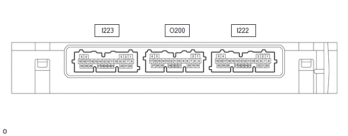
CHECK CERTIFICATION ECU (SMART KEY ECU ASSEMBLY) (w/ Smart Key System)
(a) Disconnect the I222 certification ECU (smart key ECU assembly) connector.
(b) Measure the voltage and resistance according to the value(s) in the table below.
|
Terminal No. (Symbol) | Terminal Description |
Condition | Specified Condition |
|---|---|---|---|
|
I222-29 (E) - Body ground |
Ground | Always |
Below 1 Ω |
|
I222-6 (+B) - Body ground |
Auxiliary battery power supply |
Ignition switch off | 11 to 14 V |
(c) Reconnect the O200 certification ECU (smart key ECU assembly) connector.
(d) Measure the voltage and check for pulses according to the value(s) in the table below.
|
Tester Connection | Terminal Description |
Condition | Specified Condition |
|---|---|---|---|
|
O200-16 (TSW5) - Body ground |
Back door opener switch input |
Back door opener switch assembly (open switch) off → on |
Below 1 V → Pulse generation |


