Toyota Corolla Cross: Terminals Of Ecu
TERMINALS OF ECU
|
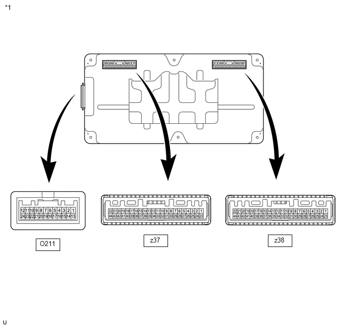
*1 | Battery ECU Assembly |
- | - |
|
Connector Code | Terminal No. |
Symbol | Terminal Description |
|---|---|---|---|
|
O211 | 1 |
TC0 | Intake air temperature sensor signal |
|
2 | GC0 |
Intake air temperature sensor ground | |
|
3 | - |
- | |
| 4 |
- | - | |
|
5 | IB0 |
Battery current sensor 0 signal | |
|
6 | IB1 |
Battery current sensor 1 signal | |
|
7 | - |
- | |
| 8 |
CA2L | CAN communication signal | |
|
9 | CA2H |
CAN communication signal | |
|
10 | GND |
Ground | |
|
11 | - |
- | |
| 12 |
IGCT | Power source | |
|
13 | FP0 |
HV battery cooling blower monitor signal | |
|
14 | SI0 |
HV battery cooling blower operation signal | |
|
15 | - |
- | |
| 16 |
- | - | |
|
17 | VIB |
Power source for battery current sensor | |
|
18 | GIB |
Battery current sensor ground | |
|
19 | C2LB |
CAN communication signal | |
|
20 | C2HB |
CAN communication signal | |
|
21 | CA1L |
CAN communication signal | |
|
22 | CA1H |
CAN communication signal | |
|
23 | - |
- | |
| 24 |
AM | Constant power source | |
|
z37 | 1 |
- | - |
|
2 | - |
- | |
| 3 |
VA29 | HV Battery Cell Voltage | |
|
4 | VA27 |
HV Battery Cell Voltage | |
|
5 | VA25 |
HV Battery Cell Voltage | |
|
6 | VA23 |
HV Battery Cell Voltage | |
|
7 | VA22 |
HV Battery Cell Voltage | |
|
8 | - |
- | |
| 9 |
VA20 | HV Battery Cell Voltage | |
|
10 | VA18 |
HV Battery Cell Voltage | |
|
11 | VA16 |
HV Battery Cell Voltage | |
|
12 | VA14 |
HV Battery Cell Voltage | |
|
13 | VA12 |
HV Battery Cell Voltage | |
|
14 | VA10 |
HV Battery Cell Voltage | |
|
15 | VA8 |
HV Battery Cell Voltage | |
|
16 | VA6 |
HV Battery Cell Voltage | |
|
17 | VA4 |
HV Battery Cell Voltage | |
|
18 | VA2 |
HV Battery Cell Voltage | |
|
19 | GA0 |
HV Battery Cell Voltage | |
|
20 | CD0 |
HV battery judgment signal | |
|
21 | TB1 |
HV battery temperature sensor 1 | |
|
22 | GB0 |
HV battery temperature sensor 0 and 2 ground | |
|
23 | VA30 |
HV Battery Cell Voltage | |
|
24 | - |
- | |
| 25 |
- | - | |
|
26 | VA28 |
HV Battery Cell Voltage | |
|
27 | VA26 |
HV Battery Cell Voltage | |
|
28 | VA24 |
HV Battery Cell Voltage | |
|
29 | GA1 |
HV Battery Cell Voltage | |
|
30 | - |
- | |
| 31 |
VA21 | HV Battery Cell Voltage | |
|
32 | VA19 |
HV Battery Cell Voltage | |
|
33 | VA17 |
HV Battery Cell Voltage | |
|
34 | VA15 |
HV Battery Cell Voltage | |
|
35 | VA13 |
HV Battery Cell Voltage | |
|
36 | VA11 |
HV Battery Cell Voltage | |
|
37 | VA9 |
HV Battery Cell Voltage | |
|
38 | VA7 |
HV Battery Cell Voltage | |
|
39 | VA5 |
HV Battery Cell Voltage | |
|
40 | VA3 |
HV Battery Cell Voltage | |
|
41 | VA1 |
HV Battery Cell Voltage | |
|
42 | GD0 |
HV battery temperature sensor 1 ground | |
|
43 | TB2 |
HV battery temperature sensor 2 | |
|
44 | TB0 |
HV battery temperature sensor 0 | |
|
z38 | 1 |
- | - |
|
2 | VA58 |
HV Battery Cell Voltage | |
|
3 | VA56 |
HV Battery Cell Voltage | |
|
4 | VA54 |
HV Battery Cell Voltage | |
|
5 | VA52 |
HV Battery Cell Voltage | |
|
6 | VA50 |
HV Battery Cell Voltage | |
|
7 | VA48 |
HV Battery Cell Voltage | |
|
8 | VA46 |
HV Battery Cell Voltage | |
|
9 | VA44 |
HV Battery Cell Voltage | |
|
10 | VA42 |
HV Battery Cell Voltage | |
|
11 | VA40 |
HV Battery Cell Voltage | |
|
12 | VA38 |
HV Battery Cell Voltage | |
|
13 | GD1 |
HV battery temperature sensor 4 ground | |
|
14 | TB5 |
HV battery temperature sensor 5 | |
|
15 | TB3 |
HV battery temperature sensor 3 | |
|
16 | VA37 |
HV Battery Cell Voltage | |
|
17 | - |
- | |
| 18 |
- | - | |
|
19 | VA36 |
HV Battery Cell Voltage | |
|
20 | VA34 |
HV Battery Cell Voltage | |
|
21 | VA32 |
HV Battery Cell Voltage | |
|
22 | VAD |
HV Battery Cell Voltage | |
|
23 | VA60 |
HV Battery Cell Voltage | |
|
24 | VA59 |
HV Battery Cell Voltage | |
|
25 | VA57 |
HV Battery Cell Voltage | |
|
26 | VA55 |
HV Battery Cell Voltage | |
|
27 | VA53 |
HV Battery Cell Voltage | |
|
28 | VA51 |
HV Battery Cell Voltage | |
|
29 | VA49 |
HV Battery Cell Voltage | |
|
30 | VA47 |
HV Battery Cell Voltage | |
|
31 | VA45 |
HV Battery Cell Voltage | |
|
32 | VA43 |
HV Battery Cell Voltage | |
|
33 | VA41 |
HV Battery Cell Voltage | |
|
34 | VA39 |
HV Battery Cell Voltage | |
|
35 | GA2 |
HV Battery Cell Voltage | |
|
36 | CD1 |
HV battery judgment signal | |
|
37 | TB4 |
HV battery temperature sensor 4 | |
|
38 | GB1 |
HV battery temperature sensor 3 and 5 ground | |
|
39 | - |
- | |
| 40 |
- | - | |
|
41 | - |
- | |
| 42 |
VA35 | HV Battery Cell Voltage | |
|
43 | VA33 |
HV Battery Cell Voltage | |
|
44 | VA31 |
HV Battery Cell Voltage |

