Toyota Corolla Cross: Supply Voltage Circuit Circuit Voltage Above Threshold (C123A17)
DESCRIPTION
The power steering ECU assembly distinguishes the ignition switch status as ON or off through the IG power source circuit.
|
DTC No. |
Detection Item |
DTC Detection Condition |
Trouble Area |
Warning Indicate |
|---|---|---|---|---|
|
C123A17 |
Supply Voltage Circuit Circuit Voltage Above Threshold |
IG voltage is 18.5 V or more |
|
EPS warning light: Comes on |
*: for HEV Model
WIRING DIAGRAM
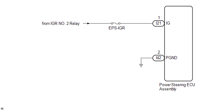
for Gasoline Model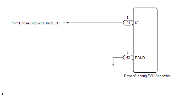 for HEV Model
CAUTION / NOTICE / HINT
NOTICE:
- When the power steering ECU assembly has been replaced, perform Power Steering
ECU Initial Setting (assist map writing).
Click here
.gif)
- Inspect the fuses for circuits related to this system before performing the following procedure.
PROCEDURE
|
1. |
CHECK HARNESS AND CONNECTOR (IG POWER SOURCE) |
(a) Disconnect the I21 power steering ECU assembly connectors.
 (to Power Steering ECU Assembly)
|
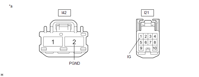
*a |
Front view of wire harness connector (to Power Steering ECU Assembly) |
- |
- |
(b) Measure the voltage according to the value(s) in the table below.
Standard Voltage:
|
Tester Connection |
Switch Condition |
Specified Condition |
|---|---|---|
|
I21-1 (IG) - Body ground |
Ignition switch ON |
8 to 16 V |
(c) Measure the resistance according to the value(s) in the table below.
Standard Resistance:
|
Tester Connection |
Condition |
Specified Condition |
|---|---|---|
|
I42-2 (PGND) - Body ground |
Always |
Below 1 Ω |
| OK | .gif) |
REPLACE POWER STEERING ECU ASSEMBLY |
| NG | |
REPAIR OR REPLACE HARNESS OR CONNECTOR |
READ NEXT:
 Power Steering Torque Sensor "A" Signal Compare Failure (C151162,C151187,C151262,C151287)
DESCRIPTION
The power steering ECU assembly supplies a voltage of 5 V to the torque sensor
(electric power steering column sub-assembly) and monitors the voltage value of
the Hall IC inside the t
Power Steering Torque Sensor "A" Supply Voltage Circuit Voltage Above Threshold
(C151A17)
DESCRIPTION
The power steering ECU assembly supplies a voltage of 5 V to the torque sensor
(electric power steering column sub-assembly) and monitors the voltage value of
the Hall IC inside the t
Power Steering Torque Sensor "B" Supply Voltage Circuit Voltage Above Threshold
(C151B17)
DESCRIPTION
The power steering ECU assembly supplies a voltage of 5 V to the torque sensor
(electric power steering column sub-assembly) and monitors the voltage value of
the Hall IC inside the t
SEE MORE:
 System Description
SYSTEM DESCRIPTION FUNCTION OF SRS CONNECTORS
(a) Location of activation prevention mechanism
(b) Function of activation prevention mechanism
(1) This mechanism is designed to create a short circuit automatically between the positive (+) and negative (-) terminals of a squib power source con
Driver Side Seat Belt Warning Light does not Operate
DESCRIPTION The combination meter assembly blinks or turns off the seat belt warning light on the combination meter assembly in accordance with the state of the front seat inner belt assembly LH. WIRING DIAGRAM
CAUTION / NOTICE / HINT
NOTICE: When replacing the combination meter assembly, alway
