Toyota Corolla Cross: Sound cannot be Heard Sound Quality is Poor only when Replaying USB Storage Device or "iPod"
WIRING DIAGRAM
CAUTION / NOTICE / HINT
NOTICE:
Depending on the parts that are replaced during vehicle inspection or maintenance, performing initialization, registration or calibration may be needed.
Click here .gif)
PROCEDURE
|
1. |
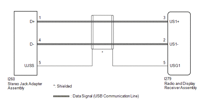
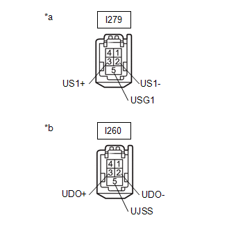
CHECK HARNESS AND CONNECTOR (RADIO AND DISPLAY RECEIVER ASSEMBLY - STEREO JACK ADAPTER ASSEMBLY) |
(a) Disconnect the I279 radio and display receiver assembly connector.
(b) Disconnect the I260 stereo jack adapter assembly connector.
|
(c) Measure the resistance according to the value(s) in the table below. Standard Resistance:
|
|
| NG | .gif)
|
REPAIR OR REPLACE HARNESS OR CONNECTOR |
|
.gif)
|
2. |
CHECK STEREO JACK ADAPTER ASSEMBLY |
(a) Replace the stereo jack adapter assembly with a new or known good one.
Click here
(b) Check if the problem symptom recurs.
|
Result |
Proceed to |
|---|---|
|
Malfunction disappears |
A |
|
Malfunction occurs |
B |
| A |
|
END (STEREO JACK ADAPTER ASSEMBLY MALFUNCTIO) |
| B |
|
REPLACE RADIO AND DISPLAY RECEIVER ASSEMBLY |
READ NEXT:
 Even though Headlights are Turned on Head-unit does not Dim the Display
WIRING DIAGRAM
CAUTION / NOTICE / HINT
NOTICE:
Depending on the parts that are replaced during vehicle inspection
or maintenance, performing initialization, registration or calibration may be n
Removal
REMOVAL
CAUTION / NOTICE / HINT
COMPONENTS (REMOVAL)
Procedure
Part Name Code
1
FRONT DOOR INSIDE HANDLE BEZEL PLUG
SEE MORE:
 Gear Shift Position Circuit Short to Battery (P091412)
DESCRIPTION
A magnet is installed to the shift fork. When the TCM commands the S1 synchronizer
to move, the shift fork moves the S1 synchronizer together and the magnet.
The Hall IC built into the shift stroke sensor converts the magnet position into
a voltage signal and sends it to the TCM. T
Odometer and trip meter
display
■ Changing the display
Press the display change button
until the desired item is displayed.
■ Display items
Odometer
Displays the total distance the vehicle
has been driven.
Trip meter A/Trip meter B
Displays the distance the vehicle
has been driven since the meter
was last reset. Trip me
