Toyota Corolla Cross: Room Temperature Sensor
Removal
REMOVAL
CAUTION / NOTICE / HINT
COMPONENTS (REMOVAL)

|
Procedure | Part Name Code |
.png) |
.png) |
.png) |
|
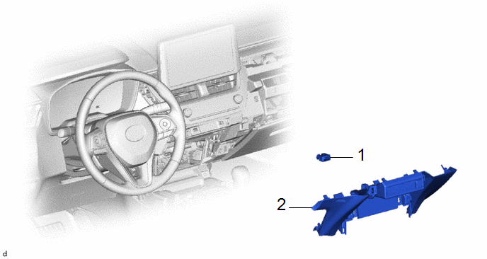
1 | LOWER CENTER INSTRUMENT PANEL FINISH PANEL |
55434F | - |
- | - |
|
2 | COOLER THERMISTOR (ROOM TEMPERATURE SENSOR) |
88625Q | - |
- | - |
PROCEDURE
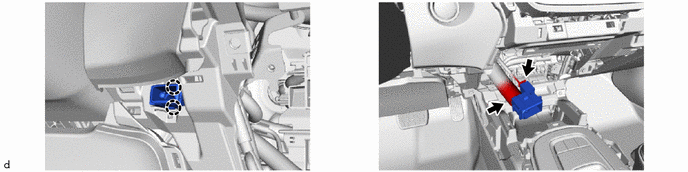
1. REMOVE LOWER CENTER INSTRUMENT PANEL FINISH PANEL
Click here
.gif)
2. REMOVE COOLER THERMISTOR (ROOM TEMPERATURE SENSOR)
Inspection
INSPECTION
PROCEDURE
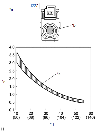
1. INSPECT COOLER THERMISTOR (ROOM TEMPERATURE SENSOR)
(a) Check the resistance.
| (1) Measure the resistance according to the value(s) in the table below.
Standard Resistance: |
Tester Connection | Condition |
Specified Condition | |
I227-1 - I227-2 | 10°C (50°F) |
3.00 to 3.73 kΩ | | I227-1 - I227-2 |
15°C (59°F) | 2.45 to 2.88 kΩ | |
I227-1 - I227-2 | 20°C (68°F) |
1.95 to 2.30 kΩ | | I227-1 - I227-2 |
25°C (77°F) | 1.60 to 1.80 kΩ | |
I227-1 - I227-2 | 30°C (86°F) |
1.28 to 1.47 kΩ | | I227-1 - I227-2 |
35°C (95°F) | 1.00 to 1.22 kΩ | |
I227-1 - I227-2 | 40°C (104°F) |
0.80 to 1.00 kΩ | | I227-1 - I227-2 |
45°C (113°F) | 0.65 to 0.85 kΩ | |
I227-1 - I227-2 | 50°C (122°F) |
0.50 to 0.70 kΩ | | I227-1 - I227-2 |
55°C (131°F) | 0.44 to 0.60 kΩ | |
I227-1 - I227-2 | 60°C (140°F) |
0.36 to 0.50 kΩ |
NOTICE:
- Hold the sensor only by its connector. Touching the sensing portion may change the resistance value.
- When measuring, the sensor temperature must be the same as the ambient temperature.
HINT: As the temperature increases, the resistance decreases (see the graph).
If the result is not as specified, replace the cooler thermistor (room temperature sensor). |
 |
|
*a | Component without harness connected
(Cooler Thermistor (Room Temperature Sensor)) | |
*b | Sensing Portion | |
*c | Resistance (kΩ) | |
*d | Temperature (°C (°F)) | |
*e | Allowable Range | | |
Installation
INSTALLATION
CAUTION / NOTICE / HINT
COMPONENTS (INSTALLATION)
|
Procedure | Part Name Code |
.png) |
.png) |
.png) |
|
1 | COOLER THERMISTOR (ROOM TEMPERATURE SENSOR) |
88625Q | - |
- | - |
|
2 | LOWER CENTER INSTRUMENT PANEL FINISH PANEL |
55434F | - |
- | - |
PROCEDURE
1. INSTALL COOLER THERMISTOR (ROOM TEMPERATURE SENSOR)
2. INSTALL LOWER CENTER INSTRUMENT PANEL FINISH PANEL
Click here .gif)
READ NEXT:
ON-VEHICLE INSPECTION PROCEDURE
1. INSPECT AUTOMATIC LIGHT CONTROL SENSOR (a) Disconnect the h1 automatic light control sensor connector.
(b) Measure the voltage and resistance according to th
REMOVAL CAUTION / NOTICE / HINT COMPONENTS (REMOVAL)
Procedure Part Name Code
1 INSTRUMENT PANEL SAFETY PAD ASSEMBLY
- -
- -
2 AUTOMATI
SEE MORE:
DISASSEMBLY
CAUTION / NOTICE / HINT
COMPONENTS (DISASSEMBLY)
Procedure
Part Name Code
1
SHIFT LEVER HOUSING BRACKET SUB-ASSEMBLY
33507
-
-
*1
READINESS MONITOR DRIVE PATTERN PURPOSE OF READINESS TESTS
The On-Board Diagnostic (OBD II) system is designed to monitor the performance of emission related components, and indicate any detected abnormalities using DTCs (Diagnostic Trouble Codes). Since various components need to be monitored


