Toyota Corolla Cross: Right Side Restraints Sensor 2 Value of Signal Protection Calculation Incorrect (B009783)
DESCRIPTION
|
DTC No. | Detection Item |
DTC Detection Condition | Trouble Area |
Warning Indicate | Test Mode / Check Mode |
|---|---|---|---|---|---|
|
B009783 | Right Side Restraints Sensor 2 Value of Signal Protection Calculation Incorrect |
One of the following conditions is met:
|
| Comes on |
Does not apply to test/check mode |
|
Vehicle Condition | |||||||
|---|---|---|---|---|---|---|---|
|
Pattern 1 | Pattern 2 |
Pattern 3 | Pattern 4 |
Pattern 5 | Pattern 6 | ||
|
Diagnosis Condition | Ignition switch ON |
○ | ○ |
○ | ○ |
○ | ○ |
|
Malfunction Status | The airbag ECU assembly detects a line short circuit signal in the side collision sensor RH circuit (bus 2). |
○ | - |
- | - |
- | - |
|
The airbag ECU assembly detects an open circuit signal in the side collision sensor RH circuit (bus 2). |
- | ○ |
- | - |
- | - | |
|
The airbag ECU assembly detects a short circuit to ground signal in the side collision sensor RH circuit (bus 2). |
- | - |
○ | - |
- | - | |
|
The airbag ECU assembly detects a short circuit to B+ signal in the side collision sensor RH circuit (bus 2). |
- | - |
- | ○ |
- | - | |
|
No. 1 side airbag sensor RH malfunction |
- | - |
- | - |
○ | - | |
|
Airbag ECU assembly malfunction |
- | - |
- | - |
- | ○ | |
|
Detection Time | 2 seconds |
2 seconds | 2 seconds |
2 seconds | 2 seconds |
2 seconds | |
|
Number of Trips | 1 trip |
1 trip | 1 trip |
1 trip | 1 trip |
1 trip | |
HINT:
DTC will be output when conditions for either of the patterns in the table above are met.
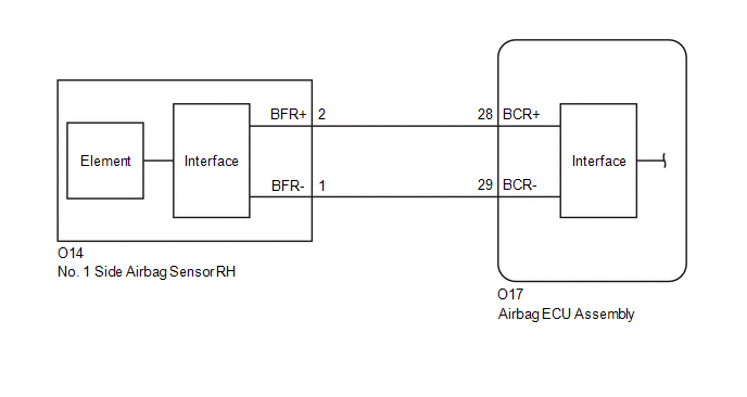
WIRING DIAGRAM
CAUTION / NOTICE / HINT
NOTICE:
After the ignition switch is turned off, there may be a waiting time before disconnecting the negative (-) battery terminal.
Click here .gif)
HINT:
When disconnecting and reconnecting the battery, there is an automatic learning function that completes learning when the respective system is used.
Click here
PROCEDURE
| 1. |
CHECK CONNECTION OF CONNECTORS |
(a) Turn the ignition switch off.
(b) Disconnect the cable from the negative (-) battery terminal.
CAUTION:
Wait at least 60 seconds after disconnecting the cable from the negative (-) battery terminal to disable the SRS system.
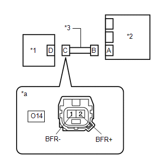
(c) Check that the connectors are properly connected to the airbag ECU assembly and No. 1 side airbag sensor RH.
OK:
The connectors are properly connected.
| NG | .gif) | CONNECT CONNECTORS PROPERLY |
|
.gif)
| 2. |
CHECK CONNECTORS |
(a) Disconnect the connectors from the airbag ECU assembly and No. 1 side airbag sensor RH.
| (b) Check that the terminals of the connectors are not deformed or damaged. OK: The terminals of the connectors are not deformed or damaged. |
|
| NG | | REPAIR OR REPLACE HARNESS OR CONNECTOR |
|
| 3. |
CHECK HARNESS AND CONNECTOR (SHORT) |
| (a) Measure the resistance according to the value(s) in the table below. Standard Resistance:
|
|
| NG | | REPAIR OR REPLACE HARNESS OR CONNECTOR |
|
| 4. |
CHECK HARNESS AND CONNECTOR (SHORT TO GROUND) |
| (a) Measure the resistance according to the value(s) in the table below. Standard Resistance:
|
|
| NG | | REPAIR OR REPLACE HARNESS OR CONNECTOR |
|
| 5. |
CHECK HARNESS AND CONNECTOR (SHORT TO B+) |
(a) Connect the cable to the negative (-) battery terminal.
(b) Turn the ignition switch to ON.
| (c) Measure the voltage according to the value(s) in the table below. Standard Voltage:
Result:
|
|
(d) Turn the ignition switch off.
(e) Disconnect the cable from the negative (-) battery terminal.
CAUTION:
Wait at least 60 seconds after disconnecting the cable from the negative (-) battery terminal to disable the SRS system.
| NG | | REPAIR OR REPLACE HARNESS OR CONNECTOR |
|
| 6. |
CHECK HARNESS AND CONNECTOR (OPEN) |
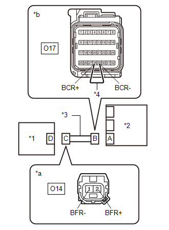
(a) Using a service wire, connect terminals 28 (BCR+) and 29 (BCR-) of connector B.
NOTICE:
Do not forcibly insert the service wire into the terminals of the connector when connecting the wire.
| (b) Measure the resistance according to the value(s) in the table below. Standard Resistance:
Result:
|
|
(c) Disconnect the service wire from connector B.
| NG | | REPAIR OR REPLACE HARNESS OR CONNECTOR |
|
| 7. |
CLEAR DTC |
| (a) Connect the connector to the airbag ECU assembly. |
|
.png)
(b) Interchange the No. 1 side airbag sensor RH with LH and connect the connectors.
(c) Connect the cable to the negative (-) battery terminal.
(d) Turn the ignition switch to ON, and wait for at least 60 seconds.
(e) Clear the DTCs stored in memory.
Body Electrical > SRS Airbag > Clear DTCs(f) Turn the ignition switch off.
|
| 8. |
CHECK NO.1 SIDE AIR BAG SENSOR RH |
(a) Turn the ignition switch to ON, and wait for at least 60 seconds.
(b) Check for DTCs.
Body Electrical > SRS Airbag > Trouble Codes| Result |
Proceed to |
|---|---|
| B009783 is output |
A |
| B009283 is output |
B |
| B009283 and B009783 are not output |
C |
HINT:
Codes other than DTCs B009283 and B009783 may be output at this time, but they are not related to this check.
(c) Turn the ignition switch off.
(d) Disconnect the cable from the negative (-) battery terminal.
CAUTION:
Wait at least 60 seconds after disconnecting the cable from the negative (-) battery terminal to disable the SRS system.
(e) Return the No. 1 side airbag sensor RH and LH to their original positions and connect the connectors.
| A |
| REPLACE AIRBAG ECU ASSEMBLY |
| B |
| REPLACE SIDE AIR BAG SENSOR NO.1 |
| C |
| USE SIMULATION METHOD TO CHECK |
READ NEXT:
 Right Side Restraints Sensor 2 Signal Below Allowable Range (B009784)
DESCRIPTION
DTC No. Detection Item
DTC Detection Condition Trouble Area
Warning Indicate Test Mode / Check Mode
B009784 Right Side Restraints Sensor 2 Signal Below Allo
Right Side Restraints Sensor 2 Signal Above Allowable Range (B009785)
DESCRIPTION
DTC No. Detection Item
DTC Detection Condition Trouble Area
Warning Indicate Test Mode / Check Mode
B009785 Right Side Restraints Sensor 2 Signal Above Allo
Right Side Restraints Sensor 2 Missing Message (B009787)
DESCRIPTION
DTC No. Detection Item
DTC Detection Condition Trouble Area
Warning Indicate Test Mode / Check Mode
B009787 Right Side Restraints Sensor 2 Missing Message
SEE MORE:
 Diagnosis System
DIAGNOSIS SYSTEM
OBD II (except Mexico Models)
When troubleshooting OBD II (On-Board Diagnostics) vehicles, the GTS (complying
with SAE J1978) must be connected to the DLC3 (Data Link Connector 3) of the vehicle.
Various data in the vehicle's TCM (Transmission Control Module) can be then
Only Wireless Control Function is Inoperative
DESCRIPTION The door control receiver receives signals from the door control transmitter assembly and sends these signals to the main body ECU (multiplex network body ECU). The main body ECU (multiplex network body ECU) then controls all doors by sending lock/unlock signals to each door, and sends h
