Toyota Corolla Cross: Right Rear Wheel Speed Sensor Supply Voltage Circuit Short to Ground or Open (C14E914)
DESCRIPTION
Refer to DTC C051212
Click here .gif)
|
DTC No. |
Detection Item |
DTC Detection Condition |
Trouble Area |
|---|---|---|---|
|
C14E914 |
Right Rear Wheel Speed Sensor Supply Voltage Circuit Short to Ground or Open |
An open or short in the speed sensor power supply circuit is detected for 0.12 seconds or more. |
|
- *1: for AWD
- *2: for 2WD
WIRING DIAGRAM
Refer to DTC C051212.
Click here
PROCEDURE
|
1. |
CHECK VEHICLE |
(a) Check the vehicle specification.
|
Result |
Proceed to |
|---|---|
|
for 2WD |
A |
|
for AWD |
B |
| B | .gif)
|
GO TO STEP 5 |
|
.gif)
|
2. |
CHECK HARNESS AND CONNECTOR (SENSOR POWER SOURCE CIRCUIT) |
|
(a) Make sure that there is no looseness at the locking part and the connecting part of the connectors. OK: The connector is securely connected. |
|
.png)
(b) Disconnect the o3 rear speed sensor RH (rear axle hub and bearing assembly RH) connector.
(c) Check both the connector case and the terminals for deformation and corrosion.
OK:
No deformation or corrosion.
(d) Turn the ignition switch to ON.
(e) Measure the voltage according to the value(s) in the table below.
Standard Voltage:
|
Tester Connection |
Condition |
Specified Condition |
|---|---|---|
|
o3-2 (RR+) - o3-1 (RR-) |
Ignition switch ON |
11 to 14 V |
| OK |
|
REPLACE REAR AXLE HUB AND BEARING ASSEMBLY RH |
|
|
3. |
CHECK HARNESS AND CONNECTOR (SENSOR POWER SOURCE CIRCUIT) |
|
(a) Make sure that there is no looseness at the locking part and the connecting part of the connectors. OK: The connector is securely connected. |
|
.png)
(b) Disconnect the oO2 skid control sensor wire RH (No. 1 parking brake wire assembly) connector.
(c) Check both the connector case and the terminals for deformation and corrosion.
OK:
No deformation or corrosion.
(d) Turn the ignition switch to ON.
(e) Measure the voltage according to the value(s) in the table below.
Standard Voltage:
|
Tester Connection |
Condition |
Specified Condition |
|---|---|---|
|
oO2-2 (RR+) - oO2-1 (RR-) |
Ignition switch ON |
11 to 14 V |
| OK |
|
REPLACE NO. 1 PARKING BRAKE WIRE ASSEMBLY |
|
|
4. |
CHECK HARNESS AND CONNECTOR (NO. 1 PARKING BRAKE WIRE ASSEMBLY - BRAKE ACTUATOR ASSEMBLY) |
(a) Make sure that there is no looseness at the locking part and the connecting part of the connectors.
OK:
The connector is securely connected.
(b) Disconnect the A151 skid control ECU (brake actuator assembly) connector.
(c) Disconnect the oO2 skid control sensor wire RH (No. 1 parking brake wire assembly) connector.
(d) Check both the connector case and the terminals for deformation and corrosion.
OK:
No deformation or corrosion.
(e) Measure the resistance according to the value(s) in the table below.
Standard Resistance:
|
Tester Connection |
Condition |
Specified Condition |
|---|---|---|
|
oO2-2 (RR+) or A151-22 (RR+) - Body ground |
Always |
10 kΩ or higher |
| OK |
|
REPLACE BRAKE ACTUATOR ASSEMBLY |
| NG |
|
REPAIR OR REPLACE HARNESS OR CONNECTOR |
|
5. |
CHECK HARNESS AND CONNECTOR (SENSOR POWER SOURCE CIRCUIT) |
|
(a) Make sure that there is no looseness at the locking part and the connecting part of the connectors. OK: The connector is securely connected. |
|
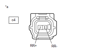
(b) Disconnect the o4 rear speed sensor RH connector.
(c) Check both the connector case and the terminals for deformation and corrosion.
OK:
No deformation or corrosion.
(d) Turn the ignition switch to ON.
(e) Measure the voltage according to the value(s) in the table below.
Standard Voltage:
|
Tester Connection |
Condition |
Specified Condition |
|---|---|---|
|
o4-1 (RR+) - o4-2 (RR-) |
Ignition switch ON |
11 to 14 V |
| OK |
|
REPLACE REAR SPEED SENSOR RH |
| NG |
|
GO TO STEP 3 |
READ NEXT:
 Brake Pressure Control Solenoid "C" Control Circuit Short to Battery (C14F112,...,C14FA49)
DESCRIPTION
The ABS solenoid relay and reservoir cut solenoid valves are
built into the brake actuator assembly.
When the brakes are operating, the reservoir cut solenoid valves
supply brake flu
Steering Angle Sensor Supply Voltage Circuit Circuit Short to Ground or Open
(C14FE14)
DESCRIPTION
This DTC is stored when the skid control ECU (brake actuator
assembly) receives a +B line open signal from the steering sensor.
DTC No.
Detection Item
Brake Switch "A" Circuit Short to Battery (P057112)
DESCRIPTION
The skid control ECU (brake actuator assembly) receives stop
light switch assembly signals and uses them to determine whether or not the brakes
are applied.
DTCs may be stored if eit
SEE MORE:
 Transmission Wire
Removal
REMOVAL
CAUTION / NOTICE / HINT
COMPONENTS (REMOVAL)
Procedure
Part Name Code
1
TRANSMISSION VALVE BODY ASSEMBLY
35410J
-
-
-
2
TRANSMIS
Installation
INSTALLATION
CAUTION / NOTICE / HINT
COMPONENTS (INSTALLATION)
Procedure
Part Name Code
1
SHIFT PADDLE SWITCH (TRANSMISSION SHIFT SWITCH ASSEMBLY)
-
-
-
