Toyota Corolla Cross: Right Rear Wheel Speed Sensor Circuit Short to Ground or Open (C051214)
DESCRIPTION
Refer to DTC C051212
Click here .gif)
|
DTC No. |
Detection Item |
DTC Detection Condition |
Trouble Area |
|---|---|---|---|
|
C051214 |
Right Rear Wheel Speed Sensor Circuit Short to Ground or Open |
A short or open circuit is detected in the speed sensor signal circuit for 0.12 seconds or more. |
|
- *1: for AWD
- *2: for 2WD
WIRING DIAGRAM
Refer to DTC C051212.
Click here
PROCEDURE
|
1. |
CHECK VEHICLE |
(a) Check the vehicle specification.
|
Result |
Proceed to |
|---|---|
|
for 2WD |
A |
|
for AWD |
B |
| B | .gif)
|
GO TO STEP 7 |
|
.gif)
|
2. |
CHECK HARNESS AND CONNECTOR (SENSOR GROUND CIRCUIT) |
|
(a) Make sure that there is no looseness at the locking part and the connecting part of the connectors. OK: The connector is securely connected. |
|
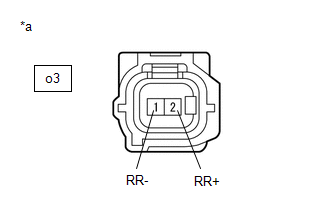
(b) Disconnect the o3 rear speed sensor RH (rear axle hub and bearing assembly RH) connector.
(c) Check both the connector case and the terminals for deformation and corrosion.
OK:
No deformation or corrosion.
(d) Turn the ignition switch to ON.
(e) Measure the voltage according to the value(s) in the table below.
Standard Voltage:
|
Tester Connection |
Condition |
Specified Condition |
|---|---|---|
|
o3-2 (RR+) - o3-1 (RR-) |
Ignition switch ON |
11 to 14 V |
| NG |
|
GO TO STEP 5 |
|
|
3. |
INSPECT NO. 1 PARKING BRAKE WIRE ASSEMBLY |
|
(a) Make sure that there is no looseness at the locking part and the connecting part of the connectors. OK: The connector is securely connected. |
|
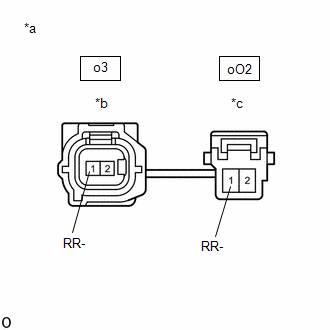
(b) Disconnect the o3 skid control sensor wire RH (No. 1 parking brake wire assembly) connector.
(c) Disconnect the oO2 skid control sensor wire RH (No. 1 parking brake wire assembly) connector.
(d) Check both the connector case and the terminals for deformation and corrosion.
OK:
No deformation or corrosion.
(e) Measure the resistance according to the value(s) in the table below.
Standard Resistance:
|
Tester Connection |
Condition |
Specified Condition |
|---|---|---|
|
o3-1 (RR-) or oO2-1 (RR-) - Body ground and other terminals |
Always |
10 kΩ or higher |
| NG |
|
REPLACE NO. 1 PARKING BRAKE WIRE ASSEMBLY |
|
|
4. |
CHECK HARNESS AND CONNECTOR (NO. 1 PARKING BRAKE WIRE ASSEMBLY - BRAKE ACTUATOR ASSEMBLY) |
(a) Make sure that there is no looseness at the locking part and the connecting part of the connectors.
OK:
The connector is securely connected.
(b) Disconnect the A151 skid control ECU (brake actuator assembly) connector.
(c) Disconnect the oO2 skid control sensor wire RH (No. 1 parking brake wire assembly) connector.
(d) Check both the connector case and the terminals for deformation and corrosion.
OK:
No deformation or corrosion.
(e) Measure the resistance according to the value(s) in the table below.
Standard Resistance:
|
Tester Connection |
Condition |
Specified Condition |
|---|---|---|
|
oO2-1 (RR-) or A151-37 (RR-) - Body ground |
Always |
10 kΩ or higher |
| OK |
|
REPLACE REAR AXLE HUB AND BEARING ASSEMBLY RH |
| NG |
|
REPAIR OR REPLACE HARNESS OR CONNECTOR |
|
5. |
INSPECT NO. 1 PARKING BRAKE WIRE ASSEMBLY |
|
(a) Make sure that there is no looseness at the locking part and the connecting part of the connectors. OK: The connector is securely connected. |
|
(b) Disconnect the o3 skid control sensor wire RH (No. 1 parking brake wire assembly) connector.
(c) Disconnect the oO2 skid control sensor wire RH (No. 1 parking brake wire assembly) connector.
(d) Check both the connector case and the terminals for deformation and corrosion.
OK:
No deformation or corrosion.
(e) Measure the resistance according to the value(s) in the table below.
Standard Resistance:
|
Tester Connection |
Condition |
Specified Condition |
|---|---|---|
|
o3-1 (RR-) - oO2-1 (RR-) |
Always |
Below 1 Ω |
| NG |
|
REPLACE NO. 1 PARKING BRAKE WIRE ASSEMBLY |
|
|
6. |
CHECK HARNESS AND CONNECTOR (NO. 1 PARKING BRAKE WIRE ASSEMBLY - BRAKE ACTUATOR ASSEMBLY) |
(a) Make sure that there is no looseness at the locking part and the connecting part of the connectors.
OK:
The connector is securely connected.
(b) Disconnect the A151 skid control ECU (brake actuator assembly) connector.
(c) Disconnect the oO2 skid control sensor wire RH (No. 1 parking brake wire assembly) connector.
(d) Check both the connector case and the terminals for deformation and corrosion.
OK:
No deformation or corrosion.
(e) Measure the resistance according to the value(s) in the table below.
Standard Resistance:
|
Tester Connection |
Condition |
Specified Condition |
|---|---|---|
|
oO2-1 (RR-) - A151-37 (RR-) |
Always |
Below 1 Ω |
| OK |
|
REPLACE BRAKE ACTUATOR ASSEMBLY |
| NG |
|
REPAIR OR REPLACE HARNESS OR CONNECTOR |
|
7. |
CHECK HARNESS AND CONNECTOR (SENSOR GROUND CIRCUIT) |
|
(a) Make sure that there is no looseness at the locking part and the connecting part of the connectors. OK: The connector is securely connected. |
|
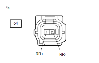
(b) Disconnect the o4 rear speed sensor RH connector.
(c) Check both the connector case and the terminals for deformation and corrosion.
OK:
No deformation or corrosion.
(d) Turn the ignition switch to ON.
(e) Measure the voltage according to the value(s) in the table below.
Standard Voltage:
|
Tester Connection |
Condition |
Specified Condition |
|---|---|---|
|
o4-1 (RR+) - o4-2 (RR-) |
Ignition switch ON |
11 to 14 V |
| NG |
|
GO TO STEP 5 |
|
|
8. |
INSPECT NO. 1 PARKING BRAKE WIRE ASSEMBLY |
|
(a) Make sure that there is no looseness at the locking part and the connecting part of the connectors. OK: The connector is securely connected. |
|
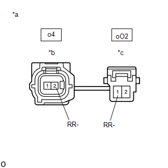
(b) Disconnect the o4 skid control sensor wire RH (No. 1 parking brake wire assembly) connector.
(c) Disconnect the oO2 skid control sensor wire RH (No. 1 parking brake wire assembly) connector.
(d) Check both the connector case and the terminals for deformation and corrosion.
OK:
No deformation or corrosion.
(e) Measure the resistance according to the value(s) in the table below.
Standard Resistance:
|
Tester Connection |
Condition |
Specified Condition |
|---|---|---|
|
o4-2 (RR-) or oO2-1 (RR-) - Body ground and other terminals |
Always |
10 kΩ or higher |
| NG |
|
REPLACE NO. 1 PARKING BRAKE WIRE ASSEMBLY |
|
|
9. |
CHECK HARNESS AND CONNECTOR (NO. 1 PARKING BRAKE WIRE ASSEMBLY - BRAKE ACTUATOR ASSEMBLY) |
(a) Make sure that there is no looseness at the locking part and the connecting part of the connectors.
OK:
The connector is securely connected.
(b) Disconnect the A151 skid control ECU (brake actuator assembly) connector.
(c) Disconnect the oO2 skid control sensor wire RH (No. 1 parking brake wire assembly) connector.
(d) Check both the connector case and the terminals for deformation and corrosion.
OK:
No deformation or corrosion.
(e) Measure the resistance according to the value(s) in the table below.
Standard Resistance:
|
Tester Connection |
Condition |
Specified Condition |
|---|---|---|
|
oO2-1 (RR-) or A151-37 (RR-) - Body ground |
Always |
10 kΩ or higher |
| OK |
|
REPLACE REAR SPEED SENSOR RH |
| NG |
|
REPAIR OR REPLACE HARNESS OR CONNECTOR |
READ NEXT:
 Right Rear Wheel Speed Sensor Circuit Voltage Out of Range (C05121C)
DESCRIPTION
Refer to DTC C051212
Click here
DTC No.
Detection Item
DTC Detection Condition
Trouble Area
C05121C
Right Rear
Right Rear Wheel Speed Sensor Circuit Intermittent (C05121F)
DESCRIPTION
Refer to DTC C051212
Click here
DTC No.
Detection Item
DTC Detection Condition
Trouble Area
C05121F
Right Rear
Right Rear Wheel Speed Sensor Signal Stuck Low (C051223)
DESCRIPTION
Refer to DTC C051212
Click here
DTC No.
Detection Item
DTC Detection Condition
Trouble Area
C051223
Right Rear
SEE MORE:
 Left Front Wheel Speed Sensor Internal Electronic Failure (C050049)
DESCRIPTION
When the system is starting up and the skid control ECU (brake
actuator assembly) detects a speed sensor circuit malfunction via the speed sensor
circuit self-diagnosis function, this DTC is stored.
DTC No.
Detection Item
DTC Detection Condition
Rear Upper Arm
Removal
REMOVAL
CAUTION / NOTICE / HINT
COMPONENTS (REOVAL)
Procedure
Part Name Code
1
REAR SUSPENSION MEMBER SUB-ASSEMBLY
51206A
-
-
-
2
REAR U
