Toyota Corolla Cross: Replacement
REPLACEMENT
CAUTION / NOTICE / HINT
The necessary procedures (adjustment, calibration, initialization, or registration) that must be performed after parts are removed and installed, or replaced during input shaft type T oil seal removal/installation are shown below.
Necessary Procedures After Parts Removed/Installed/Replaced|
Replaced Part or Performed Procedure |
Necessary Procedure |
Effect/Inoperative Function when Necessary Procedure not Performed |
Link |
|---|---|---|---|
|
Engine assembly |
Inspection after repair |
|
|
|
Front wheel alignment adjustment |
|
|
|
|
Suspension, tires, etc. |
Rear television camera assembly optical axis (Back camera position setting) |
Parking Assist Monitor System |
|
CAUTION:
- This vehicle has contains high voltage circuits standardized with orange
colored wiring and connectors, so follow the instructions in this manual to
perform the procedures correctly.
Click here
.gif)
- If the correct procedures are not followed according to the instructions in this manual, there is a danger of electric shock from the high voltage circuits.
- Be sure to wear insulating gloves when working on high voltage wiring or
components.
- If work is performed without wearing insulating gloves, there is a danger of electric shock.
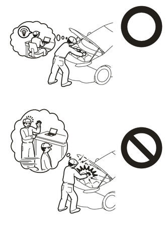
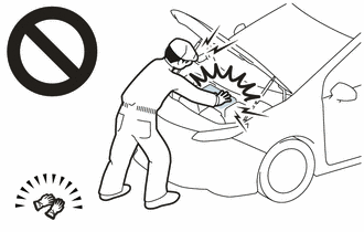
- To prevent burns, do not touch the engine, exhaust manifold or other high
temperature components while the engine is hot.
- The engine assembly with transaxle is very heavy. Be sure to follow the
procedure described in the repair manual, or the engine lifter may suddenly
drop or the engine assembly with transaxle may fall off the engine lifter.
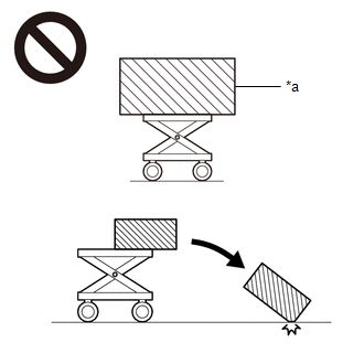
*a
An Object Exceeding Weight Limit of Engine Lifter
HINT:
When the cable is disconnected / reconnected to the auxiliary battery terminal, systems temporarily stop operating. However, each system has a function that completes learning the first time the system is used.
- Learning completes when vehicle is driven
Effect/Inoperative Function When Necessary Procedures are not Performed
Necessary Procedures
Link
Front Camera System
Drive the vehicle straight ahead at 15 km/h (10 mph) or more for 5 second or more.
- Learning completes when vehicle is operated normally
Effect/Inoperative Function When Necessary Procedures are not Performed
Necessary Procedures
Link
Power door lock control system
- Back door opener
Perform door unlock operation with door control switch or electrical key transmitter sub-assembly switch.
Power back door system
Fully close the back door by hand.
HINT:
Initialization is not necessary if the above procedures are performed while the back door is closed.
Air conditioning system
After the ignition switch is turned to ON, the servo motor standard position is recognized.
-
PROCEDURE
1. REMOVE HYBRID VEHICLE TRANSAXLE ASSEMBLY
Click here
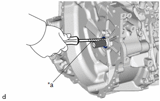
2. REMOVE INPUT SHAFT TYPE T OIL SEAL
|
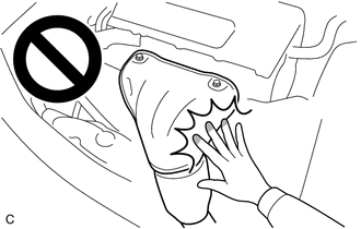
(a) Using a screwdriver with its tip wrapped with protective tape, remove the input shaft type T oil seal from the hybrid vehicle transaxle assembly. NOTICE: Be careful not to damage the input shaft assembly or hybrid vehicle transaxle assembly. |
|
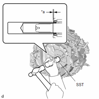
3. INSTALL INPUT SHAFT TYPE T OIL SEAL
(a) Coat the lip of a new input shaft type T oil seal with a small amount of MP grease.
|
(b) Using SST and a hammer, install the input shaft type T oil seal to the hybrid vehicle transaxle assembly. SST: 09608-04031 Standard Depth: 3.3 to 4.1 mm (0.1299 to 0.1614 in.) NOTICE:
|
|
4. INSTALL HYBRID VEHICLE TRANSAXLE ASSEMBLY
Click here


