Toyota Corolla Cross: Replacement
REPLACEMENT
CAUTION / NOTICE / HINT
The necessary procedures (adjustment, calibration, initialization, or registration) that must be performed after parts are removed and installed, or replaced during the differential side oil seal and front drive shaft oil seal RH removal/installation are shown below.
Necessary Procedures After Parts Removed/Installed/Replaced|
Replacement Part or Procedure |
Necessary Procedures |
Effect/Inoperative Function When Necessary Procedures are not Performed |
Link |
|---|---|---|---|
|
CVT fluid |
ATF thermal degradation estimate reset |
The value of the Data List item "ATF Thermal Degradation Estimate" is not estimated correctly |
|
|
Bleed air from oil pump (continuously variable transaxle assembly) |
Stop and start system |
|
|
|
Front wheel alignment adjustment |
|
|
|
|
Reset memory |
Dynamic torque control AWD system |
|
|
|
No. 2 steering intermediate shaft assembly |
End position initial setting |
Power steering system |
|
|
Suspension, tires, etc. |
Rear television camera assembly optical axis (Back camera position setting) |
Parking assist monitor system |
|
|
Initialize headlight ECU sub-assembly LH |
Automatic headlight beam level control system |
|
HINT:
When the cable is disconnected / reconnected to the auxiliary battery terminal, systems temporarily stop operating. However, each system has a function that completes learning the first time the system is used.
- Learning completes when vehicle is driven
Effect/Inoperative Function When Necessary Procedures are not Performed
Necessary Procedures
Link
Front camera system
Drive the vehicle straight ahead at 15 km/h (10 mph) or more for 1 second or more.
.gif)
Stop and start system
Drive the vehicle until stop and start control is permitted (approximately 5 to 60 minutes)
- Learning completes when vehicle is operated normally
Effect/Inoperative Function When Necessary Procedures are not Performed
Necessary Procedures
Link
Power door lock control system
- Back door opener
Perform door unlock operation with door control switch or electrical key transmitter sub-assembly switch.
Power back door system
Fully close the back door by hand.
HINT:
Initialization is not necessary if the above procedures are performed while the back door is closed.
Air conditioning system
After the ignition switch is turned to ON, the servo motor standard position is recognized.
-
PROCEDURE
1. REMOVE TRANSFER ASSEMBLY
Click here
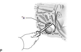
2. REMOVE DIFFERENTIAL SIDE OIL SEAL
|
(a) Using a screwdriver with its tip wrapped with protective tape, remove the differential side oil seal from the transaxle housing. NOTICE: Be careful not to damage the front differential case or transaxle housing. |
|
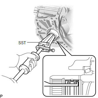
3. REMOVE FRONT DRIVE SHAFT OIL SEAL RH
|
(a) Using SST, remove the front drive shaft oil seal RH from the continuously variable transaxle assembly. SST: 09308-00010 NOTICE: Do not damage the continuously variable transaxle assembly. |
|
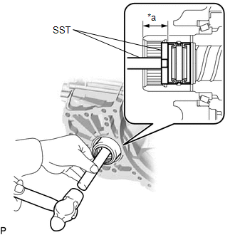
4. INSTALL FRONT DRIVE SHAFT OIL SEAL RH
(a) Coat the lip of a new front drive shaft oil seal RH with MP grease.
|
(b) Using SST and a hammer, install the front drive shaft oil seal RH to the continuously variable transaxle assembly. SST: 09950-60011 09951-00410 SST: 09950-70010 09951-07200 Standard Depth: 24.5 to 25.5 mm (0.965 to 1.004 in.) NOTICE:
|
|
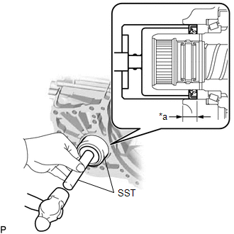
5. INSTALL DIFFERENTIAL SIDE OIL SEAL
(a) Coat the lip of a new differential side oil seal with MP grease.
|
(b) Using SST and a hammer, install the differential side oil seal to the transaxle housing. SST: 09649-17010 SST: 09950-70010 09951-07200 Standard Depth: 5.5 to 6.5 mm (0.217 to 0.256 in.) NOTICE:
|
|
6. INSTALL TRANSFER ASSEMBLY
Click here


