Toyota Corolla Cross: Removal
REMOVAL
CAUTION / NOTICE / HINT
COMPONENTS (REMOVAL)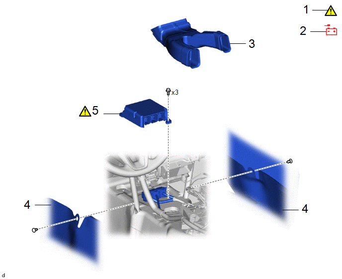
|
Procedure | Part Name Code |
.png) |
.png) |
 |
|---|---|---|---|---|---|
|
1 | PRECAUTION |
- |
|
- | - |
|
2 | CABLE FROM NEGATIVE AUXILIARY BATTERY TERMINAL |
- |
|
- | - |
|
3 | NO. 1 CONSOLE BOX DUCT |
58861B | - |
- | - |
|
4 | FRONT FLOOR CARPET ASSEMBLY |
58510D | - |
- | - |
|
5 | AIRBAG ECU ASSEMBLY |
89170A |
|
- | - |
CAUTION / NOTICE / HINT
The necessary procedures (adjustment, calibration, initialization or registration) that must be performed after parts are removed and installed, or replaced during airbag ECU assembly removal/installation are shown below.
Necessary Procedures After Parts Removed/Installed/Replaced|
Replacement Part or Procedure |
Necessary Procedures | Effect/Inoperative Function When Necessary Procedures are not Performed |
Link |
|---|---|---|---|
|
*: Even when not replacing the part, it is necessary to perform the specified necessary procedures after installation.
*A: for Gasoline Model | |||
|
Airbag ECU assembly* | ECU configuration (Only necessary after replacement) |
Vehicle Control History (RoB) are stored |
|
|
Update ECU security key (Only necessary after replacement) |
Vehicle Control History (RoB) are stored |
| |
|
Write the VIN/Vehicle Identification Number (Only necessary after replacement) |
- |
| |
|
Switch the specification information (Only necessary after replacement) |
- |
| |
|
|
| |
| Zero point calibration (Occupant classification system) |
|
| |
|
Reset memory*A | Dynamic torque control AWD system |
| |
NOTICE:
After the ignition switch is turned off, the radio and display receiver assembly records various types of memory and settings. As a result, after turning the ignition switch off, make sure to wait at least 120 seconds before disconnecting the cable from the negative (-) auxiliary battery terminal.
HINT:
When the cable is disconnected/reconnected to the auxiliary battery terminal, systems temporarily stop operating. However, each system has a function that completes learning the first time the system is used.
- Learning completes when vehicle is driven
Effect/Inoperative Function When Necessary Procedures are not Performed
Necessary Procedures
Link
*A: for Gasoline Model Front Camera System
Drive the vehicle straight ahead at 15 km/h (10 mph) or more for 1 second or more.
.gif)
Stop and start system*A
Drive the vehicle until stop and start control is permitted (approximately 5 to 60 minutes)
- Learning completes when vehicle is operated normally
Effect/Inoperative Function When Necessary Procedures are not Performed
Necessary Procedures
Link
Power door lock control system
- Back door opener
Perform door unlock operation with door control switch or electrical key transmitter sub-assembly switch.
Power back door system
Fully close the back door by hand.
HINT:
Initialization is not necessary if the above procedures are performed while the back door is closed.
Air conditioning system
After the ignition switch is turned to ON, the servo motor standard position is recognized.
-
PROCEDURE
1. PRECAUTION
|
|
CAUTION: Be sure to read Precaution thoroughly before servicing. .png)
NOTICE: After turning the ignition switch off, waiting time may be required before disconnecting the cable from the negative (-) auxiliary battery terminal. |
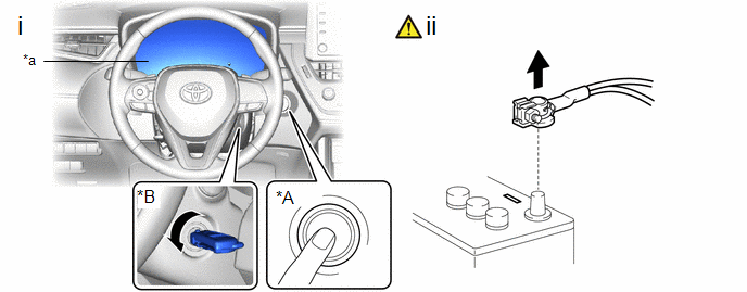
2. DISCONNECT CABLE FROM NEGATIVE AUXILIARY BATTERY TERMINAL
|
|
.png)
|
- for Gasoline Model
Click here
- for HEV Model
Click here
3. REMOVE NO. 1 CONSOLE BOX DUCT
Click here
4. REMOVE FRONT FLOOR CARPET ASSEMBLY
5. REMOVE AIRBAG ECU ASSEMBLY
|
*A | w/ Smart Key System |
*B | w/o Smart Key System |
|
*a | Illumination off |
- | - |
(1) Check that the ignition switch is off.
(2) Check that the cable is disconnected from the negative (-) auxiliary battery terminal.
CAUTION:
- Wait at least 90 seconds after disconnecting the cable from the negative (-) auxiliary battery terminal to disable the SRS system.
- If the airbag deploys for any reason, it may cause a serious accident.
.png) |
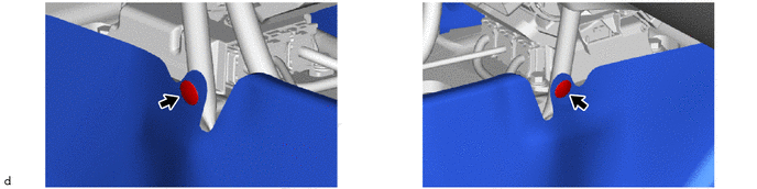
Push the Connector Lock |
.png) |
Pull Out the Lock Lever |
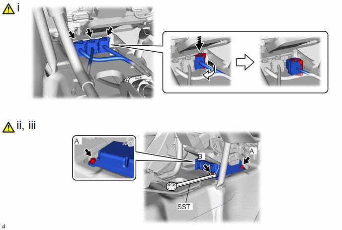
(1) Pull out each connector with its connector lock pushed to disconnect the 3 connectors.
NOTICE:
When disconnecting any airbag connector, take care not to damage the airbag wire harness.
(2) Remove the 2 bolts (A).
(3) Using SST, remove the bolt (B) and airbag ECU assembly.
SST: 09729-00120
NOTICE:
If the airbag ECU assembly has been dropped, or there are any cracks, dents or other defects in the case or connector, replace the airbag ECU assembly with a new one.


