Toyota Corolla Cross: Removal
REMOVAL
CAUTION / NOTICE / HINT
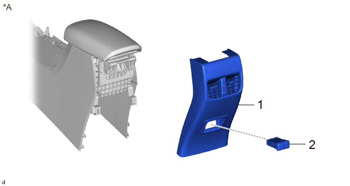
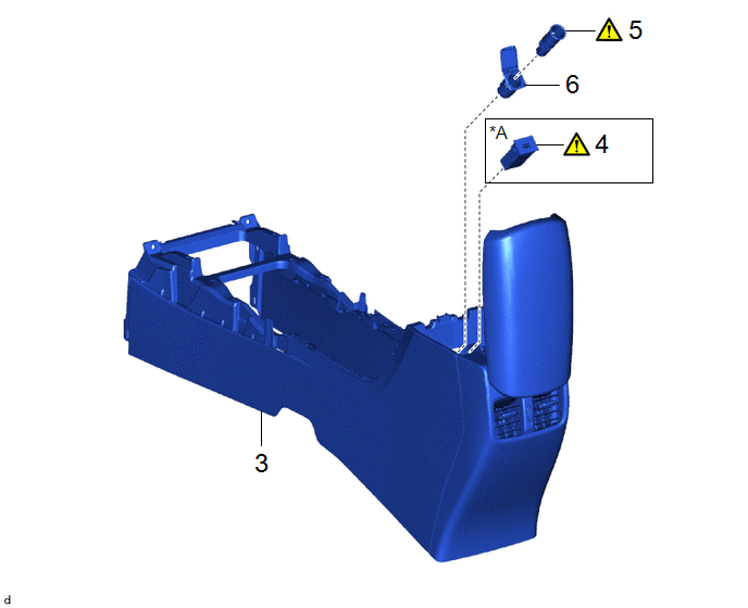
COMPONENTS (REMOVAL)
|
Procedure | Part Name Code |
.png) |
.png) |
 |
|---|---|---|---|---|---|
|
1 | CONSOLE REAR END PANEL SUB-ASSEMBLY |
- | - |
- | - |
|
2 | USB CHARGER SOCKET |
85532 | - |
- | - |
|
*A | for USB Double Charger Socket |
- | - |

|
Procedure | Part Name Code |
.png) |
.png) |
 |
|---|---|---|---|---|---|
|
3 | CONSOLE BOX ASSEMBLY |
58810J | - |
- | - |
|
4 | USB CHARGER SOCKET |
85532 |
|
- | - |
|
5 | NO. 1 POWER OUTLET SOCKET ASSEMBLY |
85530 |
|
- | - |
|
6 | NO. 1 POWER OUTLET SOCKET COVER |
85535B | - |
- | - |
|
*A | for USB Single Charger Socket |
- | - |
PROCEDURE
1. REMOVE CONSOLE REAR END PANEL SUB-ASSEMBLY (for USB Double Charger Socket)

.png) |
Remove in this Direction |
- | - |
2. REMOVE USB CHARGER SOCKET (for USB Double Charger Socket)

3. REMOVE CONSOLE BOX ASSEMBLY
Click here .gif)
.gif)
4. REMOVE USB CHARGER SOCKET (for USB Single Charger Socket)

(1) Using a screwdriver with its tip wrapped with protective tape, disengage the claws to remove the USB charger socket.
5. REMOVE NO. 1 POWER OUTLET SOCKET ASSEMBLY

(1) Using a screwdriver with its tip wrapped with protective tape, disengage the claw to remove the No. 1 power outlet socket assembly.
6. REMOVE NO. 1 POWER OUTLET SOCKET COVER


