Toyota Corolla Cross: Removal
REMOVAL
PROCEDURE
1. RECOVER REFRIGERANT FROM REFRIGERATION SYSTEM
Click here .gif)
2. REMOVE PIPING CLAMP (for Suction Hose Sub-assembly)
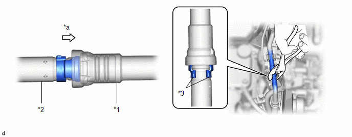
(a) for Gasoline Model:
(1) While pressing the end of the suction hose sub-assembly into the end of the suction pipe sub-assembly, use pliers to squeeze together both sides of the piping clamp until it breaks apart.
|
*1 | Suction Pipe Sub-assembly |
*2 | Suction Hose Sub-assembly |
|
*3 | Piping Clamp |
- | - |
|
*a | Press In |
- | - |
NOTICE:
- If any foreign matter is attached to the connected parts, brush it off or use compressed air to remove it before disconnecting the parts.
- Make sure that fragments of the piping clamp do not enter the piping.
(2) Separate the suction hose sub-assembly.
NOTICE:
Remove any foreign matter from the connecting parts of the suction hose sub-assembly and suction tube sub-assembly B.
(3) Remove the 2 O-rings from the suction hose sub-assembly.
NOTICE:
Seal the openings of the disconnected parts with vinyl tape to prevent entry of moisture and foreign matter.
(4) Remove the piping clamp.
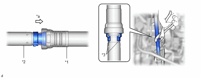
(b) for HEV Model:
(1) While pressing the end of the suction hose sub-assembly into the end of the No. 2 air conditioning tube and accessory assembly, use pliers to squeeze together both sides of the piping clamp until it breaks apart.
|
*1 | No. 2 Air Conditioning Tube and Accessory Assembly |
*2 | Suction Hose Sub-assembly |
|
*3 | Piping Clamp |
- | - |
|
*a | Press In |
- | - |
NOTICE:
- If any foreign matter is attached to the connected parts, brush it off or use compressed air to remove it before disconnecting the parts.
- Make sure that fragments of the piping clamp do not enter the piping.
(2) Separate the suction hose sub-assembly.
NOTICE:
Remove any foreign matter from the connecting parts of the suction hose sub-assembly and No. 2 air conditioning tube and accessory assembly.
(3) Remove the 2 O-rings from the suction hose sub-assembly.
NOTICE:
Seal the openings of the disconnected parts with vinyl tape to prevent entry of moisture and foreign matter.
(4) Remove the piping clamp.
3. REMOVE PIPING CLAMP (for Air Conditioning Tube and Accessory Assembly)
Click here


