Toyota Corolla Cross Owners & Service Manuals

Toyota Corolla Cross: Removal

REMOVAL

CAUTION / NOTICE / HINT

COMPONENTS (REMOVAL)
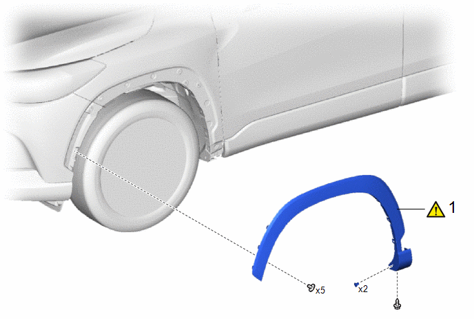
Procedure

Part Name Code

1

FRONT FENDER MOULDING SUB-ASSEMBLY

75602A

-

-

CAUTION / NOTICE / HINT

HINT:

  • Use the same procedure for the RH side and LH side.
  • The following procedure is for the LH side.

PROCEDURE

1. REMOVE FRONT FENDER MOULDING SUB-ASSEMBLY
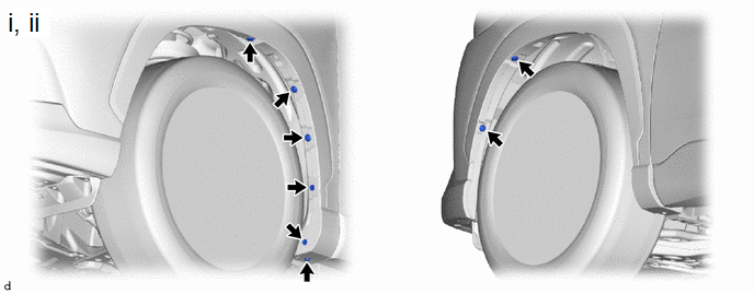
(1) Remove the screw.

(2) Remove the 5 clips and 2 grommets.
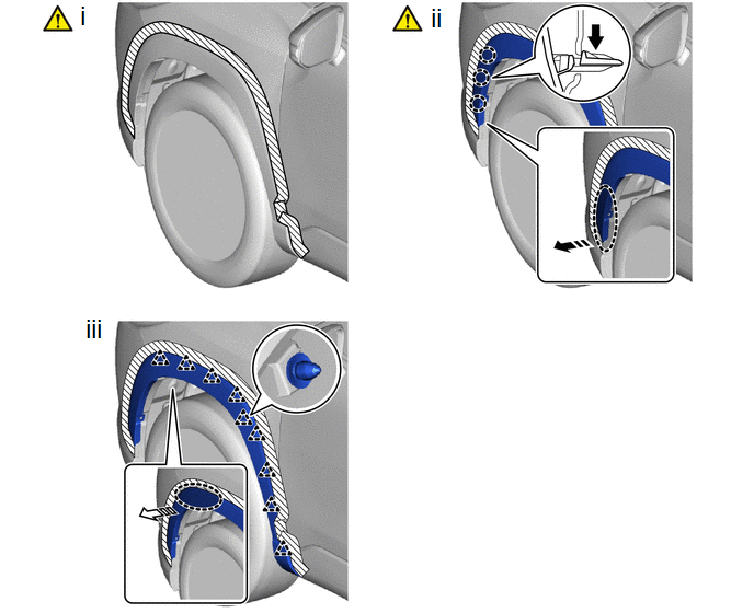
Push

Place Hand Here

Remove in this Direction (1)

Remove in this Direction (2)

(1) Apply protective tape around the front fender moulding sub-assembly as shown in the illustration.

(2) Pull back the edge of the front fender liner and disengage the claws by pushing the area indicated by the arrow in the illustration with a finger.

NOTICE:

  • Do not apply excessive force when pulling back the front fender liner.
  • To avoid damaging the claws, do not forcibly pull the front fender moulding sub-assembly.

(3) Disengage the clips to remove the front fender moulding sub-assembly as shown in the illustration.

    READ NEXT:

     Disassembly

    DISASSEMBLY CAUTION / NOTICE / HINT COMPONENTS (DISASSEMBLY) Procedure Part Name Code 1 NO. 4 FRONT WHEEL OPENING EXTENSION PAD 53854 - - - 2 NO

     Reassembly

    REASSEMBLY CAUTION / NOTICE / HINT COMPONENTS (REASSEMBLY) Procedure Part Name Code 1 NO. 5 FRONT WHEEL OPENING EXTENSION PAD 53855B - - 2

     Installation

    INSTALLATION CAUTION / NOTICE / HINT COMPONENTS (INSTALLATION) Procedure Part Name Code 1 FRONT FENDER MOULDING SUB-ASSEMBLY 75602A - - - CAUTION / NO

    SEE MORE:

     Low Beam LH Circuit Voltage Out of Range (B24441C,B24451C)

    DESCRIPTION The BIN resistance is equipped for the purpose of correcting variances in brightness (luminous flux) when the headlight ECU sub-assembly is energizing the LED with a constant current to illuminate it. Also, it monitors the voltage applied to the BIN resistance in order to detect abnorma

     Front Air Outlet Damper Control Servo Motor Actuator Stuck Off (B14037F)

    DESCRIPTION The No. 1 air conditioning radiator damper servo sub-assembly sends pulse signals to inform the air conditioning amplifier assembly of the damper position. The air conditioning amplifier assembly activates the motor (normal or reverse) based on these signals to move the air outlet damp

    © 2020-2024 Copyright www.tcorollacross.com