Toyota Corolla Cross: Removal
REMOVAL
CAUTION / NOTICE / HINT
COMPONENTS (REMOVAL)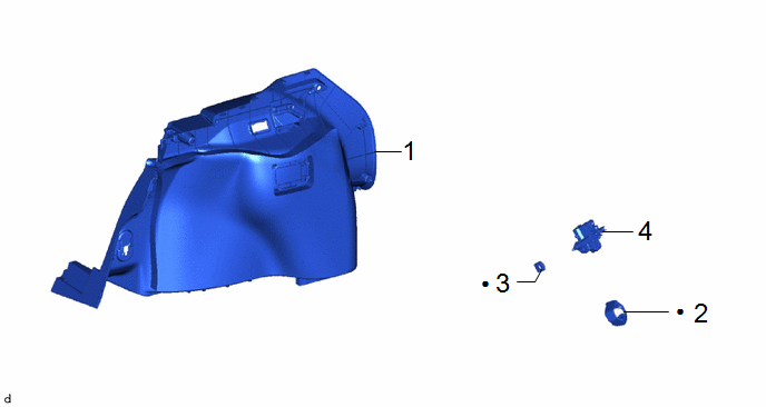
|
Procedure | Part Name Code |
.png) |
.png) |
 |
|---|---|---|---|---|---|
|
1 | DECK TRIM SIDE PANEL ASSEMBLY LH |
64740C | - |
- | - |
|
2 | FUEL FILLER OPENING LID LOCK COVER |
77378A |
|
- | - |
|
3 | FUEL FILLER OPENING LID LOCK RETAINER |
77377 |
|
- | - |
|
4 | FUEL LID LOCK WITH MOTOR ASSEMBLY |
77030A | - |
- | - |
|
● | Non-reusable part |
- | - |
CAUTION / NOTICE / HINT
The necessary procedures (adjustment, calibration, initialization, or registration) that must be performed after parts are removed, installed, or replaced during the fuel lid lock with motor assembly removal/installation are shown below.
NOTICE:
After the ignition switch is turned off, the radio receiver assembly records various types of memory and settings. As a result, after turning the ignition switch off, make sure to wait at least 85 seconds before disconnecting the cable from the negative (-) auxiliary battery terminal.
HINT:
When the cable is disconnected/reconnected to the auxiliary battery terminal, systems temporarily stop operating. However, each system has a function that completes learning the first time the system is used.
- Learning completes when vehicle is driven
Effect/Inoperative Function When Necessary Procedures are not Performed
Necessary Procedures
Link
*A: for Gasoline Model Front Camera System
Drive the vehicle straight ahead at 15km/h (10 mph) or more for 1 second ormore.
.gif)
Stop and start system
Drive the vehicle until stop and start control is permitted (approximately 5 to 60 minutes)
- Learning completes when vehicle is operated normally
Effect/Inoperative Function When Necessary Procedures are not Performed
Necessary Procedures
Link
Power door lock control system
- Back door opener
Perform door unlock operation with door control switch or electrical key transmitter sub-assembly switch.
Power back door system
Fully close the back door by hand.
HINT:
Initialization is not necessary if the above procedures are performed while the back door is closed.
Air conditioning system
After the ignition switch is turned to ON, the servo motor standard position is recognized.
-
PROCEDURE
1. REMOVE DECK TRIM SIDE PANEL ASSEMBLY LH
Click here
2. REMOVE FUEL FILLER OPENING LID LOCK COVER

.png) |
Remove in this Direction |
- | - |
3. REMOVE FUEL FILLER OPENING LID LOCK RETAINER

|
|
Remove in this Direction |
- | - |
4. REMOVE FUEL LID LOCK WITH MOTOR ASSEMBLY

|
|
Remove in this Direction |
- | - |


