Toyota Corolla Cross Owners & Service Manuals

Toyota Corolla Cross: Removal

REMOVAL

CAUTION / NOTICE / HINT

COMPONENTS (REMOVAL)
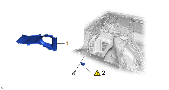
Procedure

Part Name Code

1

ROOF SIDE INNER GARNISH ASSEMBLY LH

62480A

-

-

-

2

TIRE PRESSURE WARNING ECU AND RECEIVER

897B0A

-

-

CAUTION / NOTICE / HINT

The necessary procedures (adjustment, calibration, initialization or registration) that must be performed after parts are removed and installed, or replaced during tire pressure warning ECU and receiver removal/installation are shown below.

Necessary Procedures After Parts Removed/Installed/Replaced

Replaced Part or Performed Procedure

Necessary Procedure

Effect/Inoperative Function when Necessary Procedure not Performed

Link

Tire pressure warning ECU and receiver

  • ID Registration
  • Initialization
  • Tire Position Identification

Tire Pressure Warning System

NOTICE:

When replacing the tire pressure warning ECU and receiver, read the transmitter IDs stored in the old ECU using the GTS and write them down before removal.

Click here

PROCEDURE

1. REMOVE ROOF SIDE INNER GARNISH ASSEMBLY LH

Click here

2. REMOVE TIRE PRESSURE WARNING ECU AND RECEIVER

NOTICE:

  • Do not drop the tire pressure warning ECU and receiver, strike it with tools or subject it to impact.
  • If the tire pressure warning ECU and receiver is subjected to an impact, replace it with a new one.

    READ NEXT:

     Installation

    INSTALLATION CAUTION / NOTICE / HINT COMPONENTS (INSTALLATION) Procedure Part Name Code 1 TIRE PRESSURE WARNING ECU AND

     Tire Pressure Warning System

     Precaution

    PRECAUTION TIRE PRESSURE WARNING ECU AND RECEIVER EXPRESSIONS (a) The type of tire pressure warning ECU and receiver used on this model differs according to the specifications of the vehicle. The

    SEE MORE:

     Inspection

    INSPECTION PROCEDURE 1. INSPECT WINDSHIELD WIPER SWITCH ASSEMBLY (a) Check the resistance. (1) Measure the resistance according to the value(s) in the table below. Standard Resistance: Front Wiper Switch Tester Connection Condition Specified Condition z16-14 (MIST) - z1

     Combination Switch

    Inspection INSPECTION PROCEDURE 1. INSPECT DRIVE MODE SELECT SWITCH (COMBINATION SWITCH ASSEMBLY) (a) Check the resistance. (1) Measure the resistance according to the value(s) in the table below. Standard Resistance: Tester Connection Condi

    © 2020-2025 Copyright www.tcorollacross.com