Toyota Corolla Cross: Removal
REMOVAL
CAUTION / NOTICE / HINT
COMPONENTS (REMOVAL)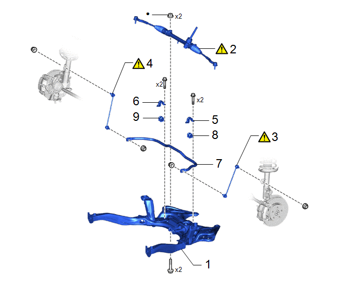
|
Procedure |
Part Name Code |
.png) |
.png) |
.png) |
|
|---|---|---|---|---|---|
|
1 |
FRONT SUSPENSION CROSSMEMBER SUB-ASSEMBLY |
51201F |
- |
- |
- |
|
2 |
STEERING LINK ASSEMBLY |
- |
|
- |
- |
|
3 |
FRONT STABILIZER LINK ASSEMBLY LH |
48810 |
|
- |
- |
|
4 |
FRONT STABILIZER LINK ASSEMBLY RH |
48820B |
|
- |
- |
|
5 |
FRONT NO. 1 STABILIZER BRACKET LH |
48829A |
- |
- |
- |
|
6 |
FRONT NO. 1 STABILIZER BRACKET RH |
48824A |
- |
- |
- |
|
7 |
FRONT STABILIZER BAR |
48811 |
- |
- |
- |
|
8 |
FRONT STABILIZER BAR BUSH LH |
48815E |
- |
- |
- |
|
9 |
FRONT STABILIZER BAR BUSH RH |
48815D |
- |
- |
- |
|
● |
Non-reusable part |
- |
- |
CAUTION / NOTICE / HINT
The necessary procedures (adjustment, calibration, initialization, or registration) that must be performed after parts are removed and installed, or replaced during front stabilizer bar removal/installation are shown below.
Necessary Procedures After Procedure Performed|
Replaced Part or Performed Procedure |
Necessary Procedure |
Effect/Inoperative Function when Necessary Procedure not Performed |
Link |
|---|---|---|---|
|
Front wheel alignment adjustment |
for HEV Model:
|
|
|
for Gasoline Model:
|
|
|
|
for Gasoline Model AWD:
|
Dynamic torque control AWD system |
|
|
|
Suspension, tires, etc. |
Rear television camera assembly optical axis (Back camera position setting) |
Parking Assist Monitor System |
|
|
Initialize headlight ECU subassembly LH |
Automatic headlight beam level control system |
|
PROCEDURE
1. REMOVE FRONT SUSPENSION CROSSMEMBER SUB-ASSEMBLY
Click here .gif)
2. REMOVE STEERING LINK ASSEMBLY
|
|
Click here |
3. REMOVE FRONT STABILIZER LINK ASSEMBLY LH
|
|
Click here |
4. REMOVE FRONT STABILIZER LINK ASSEMBLY RH
(a) Perform the same procedure as for the LH side.
5. REMOVE FRONT NO. 1 STABILIZER BRACKET LH

6. REMOVE FRONT NO. 1 STABILIZER BRACKET RH
(a) Perform the same procedure as for the LH side.
7. REMOVE FRONT STABILIZER BAR

8. REMOVE FRONT STABILIZER BAR BUSH LH

9. REMOVE FRONT STABILIZER BAR BUSH RH
(a) Perform the same procedure as for the LH side.


