Toyota Corolla Cross: Removal
REMOVAL
CAUTION / NOTICE / HINT
COMPONENTS (REMOVAL)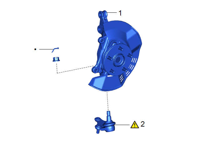
|
Procedure |
Part Name Code |
 |
 |
 |
|
|---|---|---|---|---|---|
|
1 |
FRONT AXLE ASSEMBLY |
- |
- |
- |
- |
|
2 |
FRONT LOWER BALL JOINT ASSEMBLY |
43340A |
|
- |
- |
|
● |
Non-reusable part |
- |
- |
CAUTION / NOTICE / HINT
The necessary procedures (adjustment, calibration, initialization, or registration) that must be performed after parts are removed and installed, or replaced during front lower ball joint assembly removal/installation are shown below.
Necessary Procedures After Procedure Performed|
Replaced Part or Performed Procedure |
Necessary Procedure |
Effect/Inoperative Function when Necessary Procedure not Performed |
Link |
|---|---|---|---|
|
Front wheel alignment adjustment |
for HEV Model:
|
|
|
for Gasoline Model:
|
|
|
|
for Gasoline Model AWD:
|
Dynamic torque control AWD system |
|
|
|
Suspension, tires, etc. |
Rear television camera assembly optical axis (Back camera position setting) |
Parking Assist Monitor System |
|
|
Initialize headlight ECU subassembly LH |
Automatic headlight beam level control system |
|
HINT:
- Use the same procedure for the RH side and LH side.
- The following procedure is for the LH side.
PROCEDURE
1. REMOVE FRONT AXLE ASSEMBLY
Click here .gif)
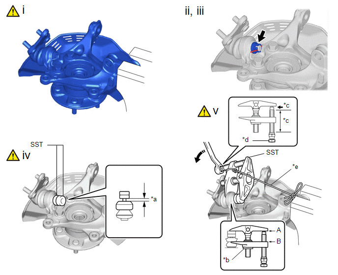
2. REMOVE FRONT LOWER BALL JOINT ASSEMBLY
|
*a |
1 mm (0.0394 in.) |
*b |
Center Nut |
|
*c |
Molybdenum Grease Application Area |
*d |
Place wrench here |
|
*e |
String |
- |
- |
 |
Turn |
- |
- |
(1) Secure the front axle assembly in a vise using aluminum plates.
NOTICE:
Do not overtighten the vise.
(2) Remove the cotter pin.
(3) Remove the nut.
(4) Install SST to the front lower ball joint assembly as shown in the illustration.
SST: 09960-20010
09961-02050
NOTICE:
Check that the clearance measurement between SST and the front axle assembly is 1 mm (0.0394 in.).
(5) Using SST, remove the front lower ball joint assembly from the front axle assembly as shown in the illustration.
SST: 09960-20010
09961-02010
09961-02050
CAUTION:
Apply molybdenum grease to the threads and end of the SST bolt.
NOTICE:
- Install SST with the center nut so that (A) and (B) shown in the illustration are parallel. Otherwise, the front lower ball joint dust cover may be damaged.
- Be sure to place a wrench on the part shown in the illustration.
- Do not damage the front lower ball joint dust cover.
- Do not damage the steering knuckle.
- Do not damage the front disc brake dust cover.


