Toyota Corolla Cross: Installation
INSTALLATION
CAUTION / NOTICE / HINT
COMPONENTS (INSTALLATION)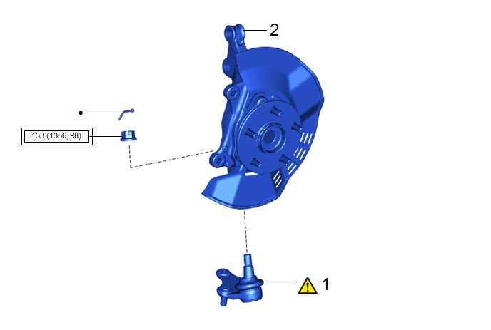
|
Procedure |
Part Name Code |
.png) |
.png) |
.png) |
|
|---|---|---|---|---|---|
|
1 |
FRONT LOWER BALL JOINT ASSEMBLY |
43340A |
|
- |
- |
|
2 |
FRONT AXLE ASSEMBLY |
- |
- |
- |
- |
 |
Tightening torque for "Major areas involving basic vehicle performance such as moving/turning/stopping" : N*m (kgf*cm, ft.*lbf) |
● |
Non-reusable part |
CAUTION / NOTICE / HINT
HINT:
- Use the same procedure for the RH side and LH side.
- The following procedure is for the LH side.
PROCEDURE
1. INSTALL FRONT LOWER BALL JOINT ASSEMBLY
(1) Secure the front axle assembly in a vise using aluminum plates.
NOTICE:
Do not overtighten the vise.
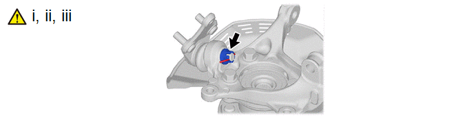
(2) Install the front lower ball joint assembly to the front axle assembly with the nut.
Torque:
133 N·m {1356 kgf·cm, 98 ft·lbf}
NOTICE:
- Do not apply lubricants to the ball joint stud taper and threads.
- Remove any foreign matter from the contact surface of the steering knuckle and ball joint stud taper.
(3) Install a new cotter pin.
NOTICE:
Further tighten the nut up to 60° if the holes for the cotter pin are not aligned.
2. INSTALL FRONT AXLE ASSEMBLY
Click here .gif)


