Toyota Corolla Cross: Removal
REMOVAL
CAUTION / NOTICE / HINT
COMPONENTS (REMOVAL)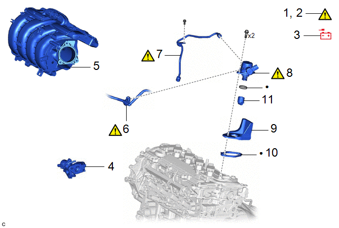
|
Procedure | Part Name Code |
.png) |
.png) |
 |
|---|---|---|---|---|---|
|
1 | PRECAUTION |
- |
|
- | - |
|
2 | DISCHARGE FUEL SYSTEM PRESSURE |
- |
|
- | - |
|
3 | DISCONNECT CABLE TO NEGATIVE AUXILIARY BATTERY TERMINAL |
- | - |
- | - |
|
4 | EGR VALVE ASSEMBLY |
25620 | - |
- | - |
|
5 | INTAKE MANIFOLD |
17111 | - |
- | - |
|
6 | FUEL TUBE SUB-ASSEMBLY |
23910A |
|
- | - |
|
7 | NO. 1 FUEL PIPE SUB-ASSEMBLY |
23801 |
|
- | - |
|
8 | FUEL(ENGINE ROOM SIDE) PUMP ASSEMBLY |
23100X |
|
- | - |
|
9 | FUEL PUMP FLANGE |
23191 | - |
- | - |
|
10 | FUEL PUMP SPACER GASKET |
23224D | - |
- | - |
|
11 | FUEL PUMP LIFTER ASSEMBLY |
23470 | - |
- | - |
|
● | Non-reusable part |
- | - |
CAUTION / NOTICE / HINT
The necessary procedures (adjustment, calibration, initialization or registration) that must be performed after parts are removed and installed, or replaced during fuel pump assembly removal/installation are shown below.
Necessary Procedures After Parts Removed/Installed/Replaced|
Replaced Part or Performed Procedure |
Necessary Procedure | Effect/Inoperative Function when Necessary Procedure not Performed |
Link |
|---|---|---|---|
| Replacement of fuel pump assembly |
Inspection after repair |
|
|
CAUTION:
- Never perform work on fuel system components near any possible ignition sources.
.png)
- Vaporized fuel could ignite, resulting in a serious accident.
- Do not perform work on fuel system components without first disconnecting the cable from the negative (-) auxiliary battery terminal.
.png)
- Sparks could cause vaporized fuel to ignite, resulting in a serious accident.
- To prevent serious injury due to fuel spray from the high-pressure fuel lines, always discharge fuel system pressure before removing any fuel system components.
.png)
NOTICE:
- After the ignition switch is turned off, the radio and display receiver assembly records various types of memory and settings. As a result, after turning the ignition switch off, make sure to wait at least 120 seconds before disconnecting the cable from the negative (-) auxiliary battery terminal.
- This procedure includes the removal of small-head bolts. Refer to Small-Head Bolts of Basic Repair Hint to identify the small-head bolts.
Click here
.gif)
HINT:
When the cable is disconnected/reconnected to the auxiliary battery terminal, systems temporarily stop operating. However, each system has a function that completes learning the first time the system is used.
- Learning completes when vehicle is driven
Effect/Inoperative Function When Necessary Procedures are not Performed
Necessary Procedures
Link
Front Camera System
Drive the vehicle straight ahead at 15 km/h (10 mph) or more for 1 second or more.
- Learning completes when vehicle is operated normally
Effect/Inoperative Function When Necessary Procedures are not Performed
Necessary Procedures
Link
Power door lock control system
- Back door opener
Perform door unlock operation with door control switch or electrical key transmitter sub-assembly switch.
Power back door system
Fully close the back door by hand.
HINT:
Initialization is not necessary if the above procedures are performed while the back door is closed.
Air conditioning system
After the ignition switch is turned to ON, the servo motor standard position is recognized.
-
PROCEDURE
1. PRECAUTION
|
|
NOTICE: After turning the ignition switch off, waiting time may be required before disconnecting the cable from the negative (-) auxiliary battery terminal. Click here |
2. DISCHARGE FUEL SYSTEM PRESSURE
Click here
3. DISCONNECT CABLE FROM NEGATIVE AUXILIARY BATTERY TERMINAL
Click here
4. REMOVE EGR VALVE ASSEMBLY
Click here
5. REMOVE INTAKE MANIFOLD
Click here
6. DISCONNECT FUEL TUBE SUB-ASSEMBLY
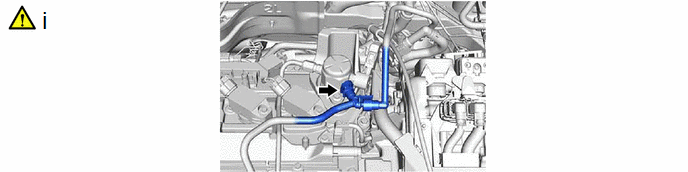
(1) Disconnect the fuel tube sub-assembly from the fuel pump assembly.
Click here
7. REMOVE NO. 1 FUEL PIPE SUB-ASSEMBLY
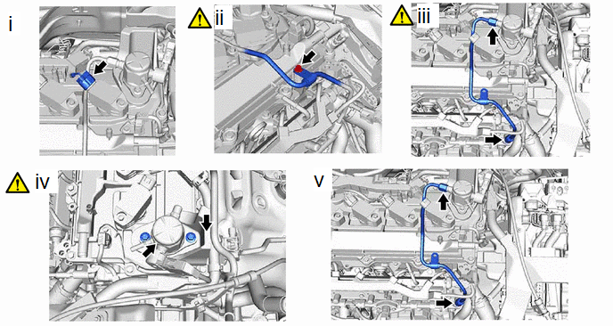
(1) Disconnect the ignition coil assembly connector.
(2) Using an 8 mm socket wrench, remove the bolt.
(3) Using a 17 mm union nut wrench, loosen the 2 union nuts of the No. 1 fuel pipe sub-assembly.
(4) Loosen the 2 bolts of the fuel pump assembly.
(5) Remove the No. 1 fuel pipe sub-assembly from the fuel delivery pipe and fuel pump assembly.
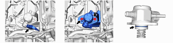
8. REMOVE FUEL (ENGINE ROOM SIDE) PUMP ASSEMBLY
|
|
NOTICE: When replacing the fuel pump assembly, it is necessary to replace the No. 1 fuel pipe sub-assembly with a new one. |
9. REMOVE FUEL PUMP FLANGE

10. REMOVE FUEL PUMP SPACER GASKET

11. REMOVE FUEL PUMP LIFTER ASSEMBLY