Toyota Corolla Cross: Removal
REMOVAL
CAUTION / NOTICE / HINT
The necessary procedures (adjustment, calibration, initialization or registration) that must be performed after parts are removed and installed, or replaced during engine unit removal/installation are shown below.
Necessary Procedures After Parts Removed/Installed/Replaced|
Replaced Part or Performed Procedure |
Necessary Procedure | Effect/Inoperative Function when Necessary Procedure not Performed |
Link |
|---|---|---|---|
| Auxiliary battery terminal is disconnected/reconnected |
End position initial setting |
Power steering system |
|
| Inspection after repair |
|
|
CAUTION / NOTICE / HINT
COMPONENTS (REMOVAL)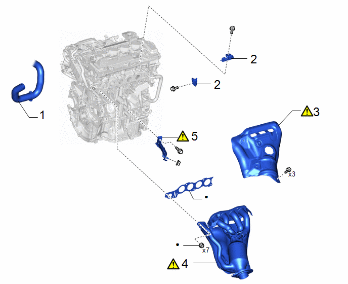
|
Procedure | Part Name Code |
.png) |
.png) |
 |
|---|---|---|---|---|---|
|
1 | NO. 2 RADIATOR HOSE |
16572D | - |
- | - |
|
2 | FUEL HOSE BRACKET |
23881B | - |
- | - |
|
3 | NO. 1 EXHAUST MANIFOLD HEAT INSULATOR |
17167 |
|
- | - |
|
4 | EXHAUST MANIFOLD |
17141 |
|
- | - |
|
5 | MANIFOLD STAY |
17118 |
|
- | - |
|
● | Non-reusable part |
- | - |
|
Procedure | Part Name Code |
|
|
| |
|---|---|---|---|---|---|
|
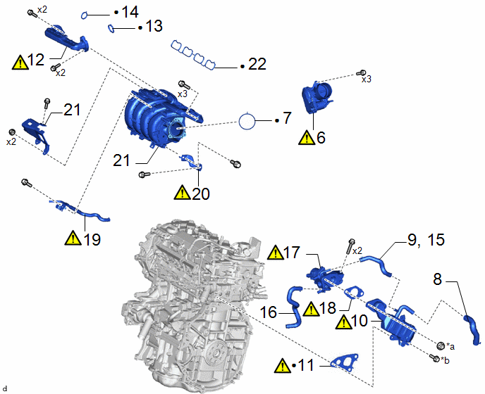
6 | THROTTLE BODY WITH MOTOR ASSEMBLY |
22030 |
|
- | - |
|
7 | THROTTLE BODY GASKET |
22271 | - |
- | - |
|
8 | NO. 3 WATER BY-PASS HOSE |
16267 | - |
- | - |
|
9 | NO. 4 WATER BY-PASS HOSE |
16281 | - |
- | - |
|
10 | EGR COOLER ASSEMBLY |
25680 |
|
- | - |
|
11 | NO. 1 EGR COOLER GASKET |
25685 |
|
- | - |
|
12 | NO. 1 EGR PIPE SUB-ASSEMBLY |
25601 |
|
- | - |
|
13 | EGR VALVE ADAPTER GASKET |
25629 | - |
- | - |
|
14 | EGR INLET GASKET |
25628 | - |
- | - |
|
15 | NO. 4 WATER BY-PASS HOSE |
16281 | - |
- | - |
|
16 | DISCONNECT NO. 8 WATER BY-PASS HOSE |
16296 | - |
- | - |
|
17 | EGR VALVE ASSEMBLY |
25620 |
|
- | - |
|
18 | REMOVE EGR VALVE GASKET |
25627 |
|
- | - |
|
19 | NO. 3 WATER BY-PASS PIPE |
16279 |
|
- | - |
|
20 | INTAKE MANIFOLD STAY |
17138B |
|
- | - |
|
21 | INTAKE MANIFOLD |
17111 | - |
- | - |
|
22 | NO. 1 INTAKE MANIFOLD TO HEAD GASKET |
17177 | - |
- | - |
|
*a | x2 or x3 |
*b | x3 or x2 |
|
● | Non-reusable part |
- | - |
|
Procedure | Part Name Code |
|
|
| |
|---|---|---|---|---|---|
|
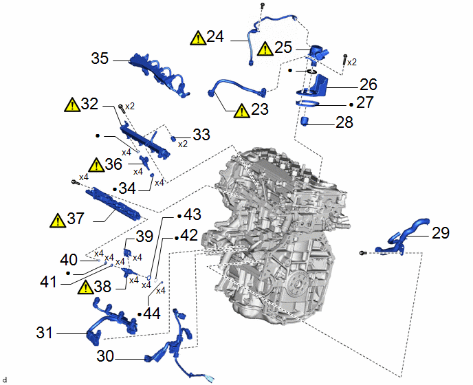
23 | FUEL TUBE SUB-ASSEMBLY |
23910A |
|
- | - |
|
24 | NO. 1 FUEL PIPE SUB-ASSEMBLY |
23801P |
|
- | - |
|
25 | FUEL (ENGINE ROOM SIDE) PUMP ASSEMBLY (for High Pressure) |
23100X |
|
- | - |
|
26 | FUEL PUMP FLANGE |
23191 | - |
- | - |
|
27 | FUEL PUMP SPACER GASKET |
23224D | - |
- | - |
|
28 | FUEL PUMP LIFTER ASSEMBLY |
23470 | - |
- | - |
|
29 | WATER BY-PASS HOSE ASSEMBLY |
- | - |
- | - |
|
30 | SENSOR WIRE |
82219C | - |
- | - |
|
31 | NO. 6 ENGINE WIRE |
82126A | - |
- | - |
|
32 | FUEL DELIVERY PIPE SUB-ASSEMBLY |
23807 |
|
- | - |
|
33 | FUEL DELIVERY SPACER |
23891 | - |
- | - |
|
34 | INJECTOR VIBRATION INSULATOR |
23291 | - |
- | - |
|
35 | NO. 5 ENGINE WIRE |
82125N | - |
- | - |
|
36 | PORT FUEL INJECTOR ASSEMBLY |
23250F |
|
- | - |
|
37 | FUEL DELIVERY PIPE |
23841B |
|
- | - |
|
38 | DIRECT FUEL INJECTOR ASSEMBLY |
23250E |
|
- | - |
|
39 | NOZZLE HOLDER CLAMP |
23695A | - |
- | - |
|
40 | NO. 3 FUEL INJECTOR BACK-UP RING |
23258 | - |
- | - |
|
41 | NO. 1 FUEL INJECTOR BACK-UP RING |
23256 | - |
- | - |
|
42 | C-RING |
- | - |
- | - |
|
43 | INJECTOR VIBRATION INSULATOR |
23291A | - |
- | - |
|
44 | INJECTOR SEAL |
23255A | - |
- | - |
|
● | Non-reusable part |
- | - |
|
Procedure | Part Name Code |
|
|
| |
|---|---|---|---|---|---|
|
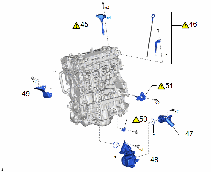
45 | IGNITION COIL ASSEMBLY |
19500 |
|
- | - |
|
46 | ENGINE OIL LEVEL DIPSTICK GUIDE |
11452D |
|
- | - |
|
47 | WATER INLET WITH THERMOSTAT SUB-ASSEMBLY |
16031 | - |
- | - |
|
48 | ENGINE WATER PUMP ASSEMBLY (WATER INLET HOUSING) |
16032 | - |
- | - |
|
49 | NO. 3 EXHAUST MANIFOLD HEAT INSULATOR |
17169A | - |
- | - |
|
50 | WIRE HARNESS CLAMP BRACKET |
- |
|
- | - |
|
● | Non-reusable part |
- | - |
PROCEDURE
1. DISCONNECT NO. 2 RADIATOR HOSE

2. REMOVE FUEL HOSE BRACKET

3. REMOVE NO. 1 EXHAUST MANIFOLD HEAT INSULATOR
|
|
Click here |
4. REMOVE EXHAUST MANIFOLD
|
|
Click here |
5. REMOVE MANIFOLD STAY
|
|
Click here |
6. REMOVE THROTTLE BODY WITH MOTOR ASSEMBLY
|
|
Click here |
7. REMOVE THROTTLE BODY GASKET
Click here
.gif)
8. DISCONNECT NO. 3 WATER BY-PASS HOSE
Click here
9. DISCONNECT NO. 4 WATER BY-PASS HOSE
Click here
10. REMOVE EGR COOLER ASSEMBLY
|
|
Click here |
11. REMOVE NO. 1 EGR COOLER GASKET
|
|
Click here |
12. REMOVE NO. 1 EGR PIPE SUB-ASSEMBLY
|
|
Click here |
13. REMOVE EGR VALVE ADAPTER GASKET
Click here
14. REMOVE EGR INLET GASKET
Click here
15. DISCONNECT NO. 4 WATER BY-PASS HOSE
Click here
16. DISCONNECT NO. 8 WATER BY-PASS HOSE
Click here
17. REMOVE EGR VALVE ASSEMBLY
|
|
Click here |
18. REMOVE EGR VALVE GASKET
|
|
Click here |
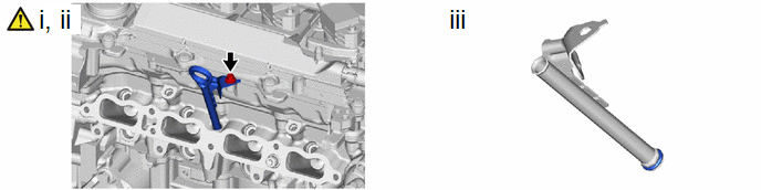
19. REMOVE NO. 3 WATER BY-PASS PIPE
(1) Using an 8 mm socket wrench, remove the bolt and No. 3 water by-pass pipe from the intake manifold.
(2) Slide the clip and disconnect the No. 3 water by-pass pipe from the water outlet sub-assembly.
20. REMOVE INTAKE MANIFOLD STAY
|
|
Click here |
21. REMOVE INTAKE MANIFOLD
Click here
22. REMOVE NO. 1 INTAKE MANIFOLD TO HEAD GASKET
Click here
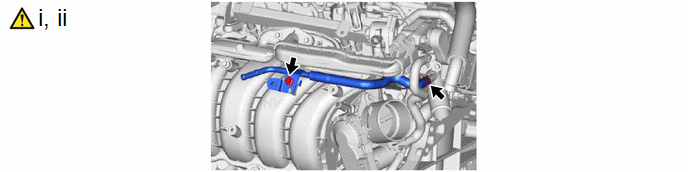
23. DISCONNECT FUEL TUBE SUB-ASSEMBLY
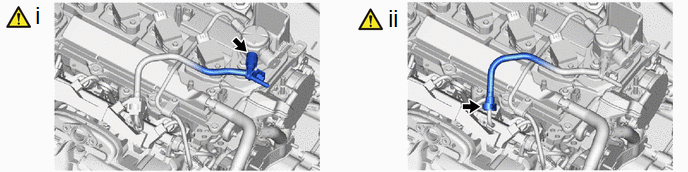
(1) Disconnect the fuel tube sub-assembly from the fuel pump assembly.
HINT:
Click here
(2) Disconnect the fuel tube sub-assembly from the fuel delivery pipe with sensor assembly.
HINT:
Click here
24. REMOVE NO. 1 FUEL PIPE SUB-ASSEMBLY
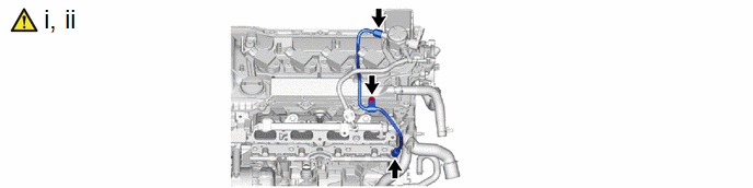
(1) Remove the bolt.
(2) Using a 17 mm union nut wrench, loosen the 2 union nuts of the No. 1 fuel pipe sub-assembly.
25. REMOVE FUEL (ENGINE ROOM SIDE) PUMP ASSEMBLY (for High Pressure)
|
|
Click here |
26. REMOVE FUEL PUMP FLANGE
Click here
27. REMOVE FUEL PUMP SPACER GASKET
28. REMOVE FUEL PUMP LIFTER ASSEMBLY
29. REMOVE WATER BY-PASS HOSE ASSEMBLY

30. REMOVE SENSOR WIRE

31. REMOVE NO. 6 ENGINE WIRE

32. REMOVE FUEL DELIVERY PIPE SUB-ASSEMBLY
|
|
Click here |
33. REMOVE FUEL DELIVERY SPACER
Click here
34. REMOVE INJECTOR VIBRATION INSULATOR
Click here
35. REMOVE NO. 5 ENGINE WIRE
Click here
36. REMOVE PORT FUEL INJECTOR ASSEMBLY
|
|
Click here |
37. REMOVE FUEL DELIVERY PIPE
|
|
Click here |
38. REMOVE DIRECT FUEL INJECTOR ASSEMBLY
|
|
Click here |
39. REMOVE NOZZLE HOLDER CLAMP
Click here
40. REMOVE NO. 3 FUEL INJECTOR BACK-UP RING
Click here
41. REMOVE NO. 1 FUEL INJECTOR BACK-UP RING
Click here
42. REMOVE C-RING
Click here
43. REMOVE INJECTOR VIBRATION INSULATOR
Click here
44. REMOVE FUEL INJECTOR SEAL
Click here
45. REMOVE IGNITION COIL ASSEMBLY
|
|
Click here |
46. REMOVE ENGINE OIL LEVEL DIPSTICK GUIDE
(1) Remove the engine oil level dipstick.
(2) Using an 8 mm socket wrench, remove the bolt and engine oil level dipstick guide from the cylinder head sub-assembly.
(3) Remove the O-ring from the engine oil level dipstick guide.
47. REMOVE WATER INLET WITH THERMOSTAT SUB-ASSEMBLY
Click here
48. REMOVE ENGINE WATER PUMP ASSEMBLY (WATER INLET HOUSING)

49. REMOVE NO. 3 EXHAUST MANIFOLD HEAT INSULATOR

50. REMOVE WIRE HARNESS CLAMP BRACKET
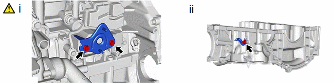
(1) Using an 8 mm socket wrench, remove the 2 bolts and wire harness clamp bracket from the No. 1 ventilation case.
(2) Remove the bolt and wire harness clamp bracket from the stiffening crankcase assembly.


