Toyota Corolla Cross: Removal
REMOVAL
CAUTION / NOTICE / HINT
COMPONENTS (REMOVAL)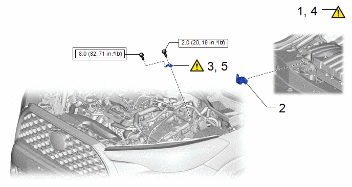
|
Procedure | Part Name Code |
.png) |
.png) |
 |
|---|---|---|---|---|---|
|
1 | PRECAUTION |
- |
|
- | - |
|
2 | SERVICE PLUG GRIP |
G3834 | - |
- | - |
|
3 | REMOVE CONNECTOR COVER ASSEMBLY |
- |
|
- | - |
|
4 | TERMINAL VOLTAGE |
- |
|
- | - |
|
5 | INSTALL CONNECTOR COVER ASSEMBLY |
- |
|
- | - |
.png) |
Tightening torque for "Major areas involving basic vehicle performance such as moving/turning/stopping" : N*m (kgf*cm, ft.*lbf) |
.png) |
N*m (kgf*cm, ft.*lbf): Specified torque |
|
Procedure | Part Name Code |
|
|
| |
|---|---|---|---|---|---|
|
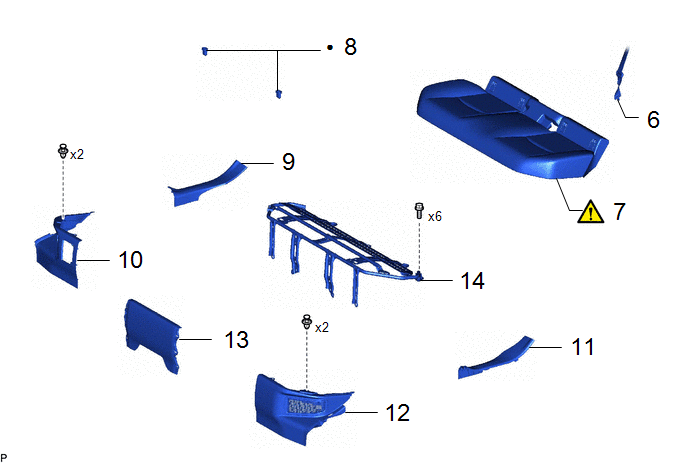
6 | REAR CENTER SEAT OUTER BELT ASSEMBLY |
73350C | - |
- | - |
|
7 | BENCH TYPE REAR SEAT CUSHION ASSEMBLY |
- |
|
- | - |
|
8 | REAR SEAT CUSHION LOCK HOOK |
72693 | - |
- | - |
|
9 | REAR DOOR SCUFF PLATE RH |
67917A | - |
- | - |
|
10 | REAR UNDER SIDE COVER RH |
76973F | - |
- | - |
|
11 | REAR DOOR SCUFF PLATE LH |
67918A | - |
- | - |
|
12 | REAR UNDER SIDE COVER LH |
76974F | - |
- | - |
|
13 | REAR UNDER COVER |
76971G | - |
- | - |
|
14 | REAR SEAT CUSHION LEG SUB-ASSEMBLY |
71033 | - |
- | - |
|
● | Non-reusable part |
- | - |
|
Procedure | Part Name Code |
|
|
| |
|---|---|---|---|---|---|
|
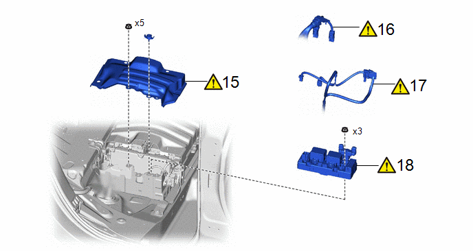
15 | NO. 1 HYBRID BATTERY SHIELD SUB-ASSEMBLY |
G920Q |
|
- | - |
|
16 | FLOOR UNDER WIRE |
821H1 |
|
- | - |
|
17 | FLOOR WIRE |
82161 |
|
- | - |
|
18 | NO. 1 TRACTION BATTERY DEVICE BOX |
G384B |
|
- | - |
CAUTION / NOTICE / HINT
The necessary procedures (adjustment, calibration, initialization, or registration) that must be performed after parts are removed and installed, or replaced during HV battery junction block assembly removal/installation are shown below.
Necessary Procedures After Parts Removed/Installed/Replaced|
Replaced Part or Performed Procedure |
Necessary Procedures |
Effect/Inoperative Function when Necessary Procedure not Performed |
Link |
|---|---|---|---|
| Replacement of HV battery junction block assembly |
Current sensor offset learning | DTCs are stored |
|
CAUTION:
- Orange wire harnesses and connectors indicate high-voltage circuits. To prevent electric shock, always follow the procedure described in the repair manual.
.png)
Click here
.gif)
- To prevent electric shock, wear insulated gloves when working on wire harnesses and components of the high voltage system.
.png)
HINT:
When the cable is disconnected / reconnected to the auxiliary battery terminal, systems temporarily stop operating. However, each system has a function that completes learning the first time the system is used.
- Learning completes when vehicle is driven.
Effect/Inoperative Function When Necessary Procedures are not Performed
Necessary Procedures
Link
Front Camera System
Drive the vehicle straight ahead at 15 km/h (10 mph) or more for 1 second or more.
- Learning completes when vehicle is operated normally
Effect/Inoperative Function When Necessary Procedures are not Performed
Necessary Procedures
Link
Power door lock control system
- Back door opener
Perform door unlock operation with door control switch or electrical key transmitter sub-assembly switch.
Power back door system
Fully close the back door by hand.
HINT:
Initialization is not necessary if the above procedures are performed while the back door is closed.
Air conditioning system
After the ignition switch is turned to ON, the servo motor standard position is recognized.
-
PROCEDURE
1. PRECAUTION
|
|
NOTICE: After turning the ignition switch off, waiting time may be required before disconnecting the cable from the negative (-) auxiliary battery terminal. Click here |
2. REMOVE SERVICE PLUG GRIP
Click here
3. REMOVE CONNECTOR COVER ASSEMBLY
|
|
Click here |
4. CHECK TERMINAL VOLTAGE
|
|
Click here |
5. INSTALL CONNECTOR COVER ASSEMBLY
|
|
Click here |
6. DISCONNECT REAR CENTER SEAT OUTER BELT ASSEMBLY
Click here
7. REMOVE BENCH TYPE REAR SEAT CUSHION ASSEMBLY
Click here
8. REMOVE REAR SEAT CUSHION LOCK HOOK
Click here
9. REMOVE REAR DOOR SCUFF PLATE RH
Click here
10. REMOVE REAR UNDER SIDE COVER RH
Click here
11. REMOVE REAR DOOR SCUFF PLATE LH
(a) Use the same procedure as for the RH side.
12. REMOVE REAR UNDER SIDE COVER LH
(a) Use the same procedure as for the RH side.
13. REMOVE REAR UNDER COVER
Click here
14. REMOVE REAR SEAT CUSHION LEG SUB-ASSEMBLY
Click here
15. REMOVE NO. 1 HYBRID BATTERY SHIELD SUB-ASSEMBLY
|
|
Click here |
16. DISCONNECT FLOOR UNDER WIRE
|
|
Click here |
17. DISCONNECT FLOOR WIRE
|
|
CAUTION: Be sure to wear insulated gloves and protective goggles. |

18. REMOVE NO. 1 TRACTION BATTERY DEVICE BOX
|
|
CAUTION: Be sure to wear insulated gloves and protective goggles. |
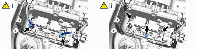
(1) Disconnect the 2 No. 1 traction battery device box assembly connectors.
NOTICE:
Insulate the disconnected high-voltage connectors with insulating tape.
(2) Remove the 3 nuts and No. 1 traction battery device box assembly from the No. 1 hybrid battery shield sub-assembly.
NOTICE:
If the No. 1 traction battery device box assembly has been struck or dropped, replace it with a new one.


