Toyota Corolla Cross: Removal
REMOVAL
CAUTION / NOTICE / HINT
COMPONENTS (REMOVAL)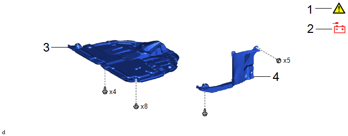
|
Procedure |
Part Name Code |
.png) |
.png) |
.png) |
|
|---|---|---|---|---|---|
|
1 |
PRECAUTION |
- |
|
- |
- |
|
2 |
DISCONNECT CABLE FROM NEGATIVE AUXILIARY BATTERY TERMINAL |
- |
- |
- |
- |
|
3 |
NO. 1 ENGINE UNDER COVER ASSEMBLY |
51410 |
- |
- |
- |
|
4 |
REAR ENGINE UNDER COVER LH |
51444A |
- |
- |
- |
|
Procedure |
Part Name Code |
|
|
|
|
|---|---|---|---|---|---|
|
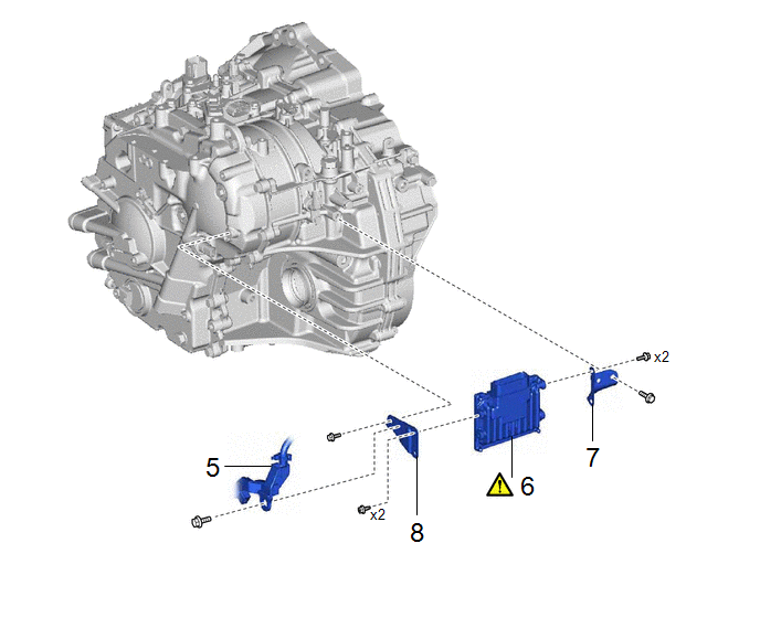
5 |
ENGINE WIRE |
82121 |
- |
- |
- |
|
6 |
TCM |
89535B |
|
- |
- |
|
7 |
NO. 1 TRANSMISSION CONTROL ECU BRACKET |
89539M |
- |
- |
- |
|
8 |
NO. 2 TRANSMISSION CONTROL ECU BRACKET |
89539N |
- |
- |
- |
CAUTION / NOTICE / HINT
The necessary procedures (adjustment, calibration, initialization, or registration) that must be performed after parts are removed and installed, or replaced during the TCM removal/installation are shown below.
Necessary Procedures After Parts Removed/Installed/Replaced|
Replacement Part or Procedure |
Necessary Procedures |
Effect/Inoperative Function When Necessary Procedures are not Performed |
Link |
|---|---|---|---|
|
TCM |
If possible, read the transaxle compensation code from the previous ECM:
|
Deterioration of fuel efficiency |
for Initialization:
for Registration:
|
|
If impossible, read the transaxle compensation code from the previous ECM:
|
|||
|
Update ECU security key |
Vehicle control history (RoB) are stored |
|
HINT:
When the cable is disconnected / reconnected to the auxiliary battery terminal, systems temporarily stop operating. However, each system has a function that completes learning the first time the system is used.
- Learning completes when vehicle is driven
Effect/Inoperative Function When Necessary Procedures are not Performed
Necessary Procedures
Link
Front camera system
Drive the vehicle straight ahead at 15 km/h (10 mph) or more for 1 second or more.
.gif)
Stop and start system
Drive the vehicle until stop and start control is permitted (approximately 5 to 60 minutes)
- Learning completes when vehicle is operated normally
Effect/Inoperative Function When Necessary Procedures are not Performed
Necessary Procedures
Link
Power door lock control system
- Back door opener
Perform door unlock operation with door control switch or electrical key transmitter sub-assembly switch.
Power back door system
Fully close the back door by hand.
HINT:
Initialization is not necessary if the above procedures are performed while the back door is closed.
Air conditioning system
After the ignition switch is turned to ON, the servo motor standard position is recognized.
-
PROCEDURE
1. PRECAUTION
|
|
NOTICE: After turning the ignition switch off, waiting time may be required before disconnecting the cable from the negative (-) auxiliary battery terminal. Click here |
2. DISCONNECT CABLE FROM NEGATIVE AUXILIARY BATTERY TERMINAL
Click here
3. REMOVE NO. 1 ENGINE UNDER COVER ASSEMBLY
Click here
4. REMOVE REAR ENGINE UNDER COVER LH
Click here
5. SEPARATE ENGINE WIRE

6. REMOVE TCM
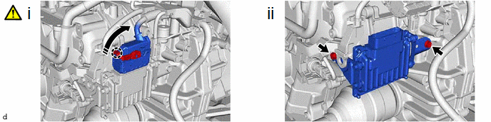
(1) Disengage the claw, rotate the lever and disconnect the connector.
(2) Remove the 2 bolts and TCM from the continuously variable transaxle assembly.
7. REMOVE NO. 1 TRANSMISSION CONTROL ECU BRACKET

8. REMOVE NO. 2 TRANSMISSION CONTROL ECU BRACKET