Toyota Corolla Cross: Removal
REMOVAL
CAUTION / NOTICE / HINT
COMPONENTS (REMOVAL)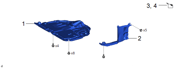
|
Procedure |
Part Name Code |
.png) |
.png) |
.png) |
|
|---|---|---|---|---|---|
|
1 |
NO. 1 ENGINE UNDER COVER ASSEMBLY |
51410 |
- |
- |
- |
|
2 |
REAR ENGINE UNDER COVER LH |
51444A |
- |
- |
- |
|
3 |
DRAIN ENGINE COOLANT |
- |
- |
|
- |
|
4 |
DRAIN CONTINUOUSLY VARIABLE TRANSAXLE FLUID |
- |
- |
|
- |
|
Procedure |
Part Name Code |
|
|
|
|
|---|---|---|---|---|---|
|
5 |
INLET WATER HOSE |
16262 |
- |
- |
- |
|
6 |
NO. 2 WATER BY-PASS HOSE |
16264D |
- |
- |
- |
|
7 |
TRANSMISSION OIL COOLER |
33493C |
- |
- |
- |
|
● |
Non-reusable part |
- |
- |
CAUTION / NOTICE / HINT
The necessary procedures (adjustment, calibration, initialization, or registration) that must be performed after parts are removed and installed, or replaced during the transmission oil cooler removal/installation are shown below.
Necessary Procedure After Parts Removed/Installed/Replaced|
Replacement Part or Procedure |
Necessary Procedures |
Effect/Inoperative Function When Necessary Procedures are not Performed |
Link |
|---|---|---|---|
|
CVT fluid |
ATF thermal degradation estimate reset |
The value of the Data List item "ATF Thermal Degradation Estimate" is not estimated correctly |
|
|
Bleed air from oil pump (continuously variable transaxle assembly) |
Stop and start system |
|
PROCEDURE
1. REMOVE NO. 1 ENGINE UNDER COVER ASSEMBLY
Click here .gif)
2. REMOVE REAR ENGINE UNDER COVER LH
Click here
3. DRAIN ENGINE COOLANT
Click here
4. DRAIN CONTINUOUSLY VARIABLE TRANSAXLE FLUID
Click here
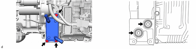
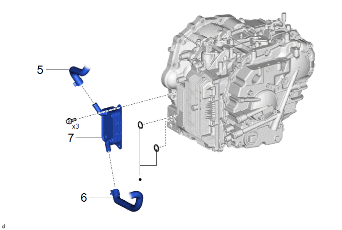
5. DISCONNECT INLET WATER HOSE

6. DISCONNECT NO. 2 WATER BY-PASS HOSE

7. REMOVE TRANSMISSION OIL COOLER