Toyota Corolla Cross: Removal
REMOVAL
CAUTION / NOTICE / HINT
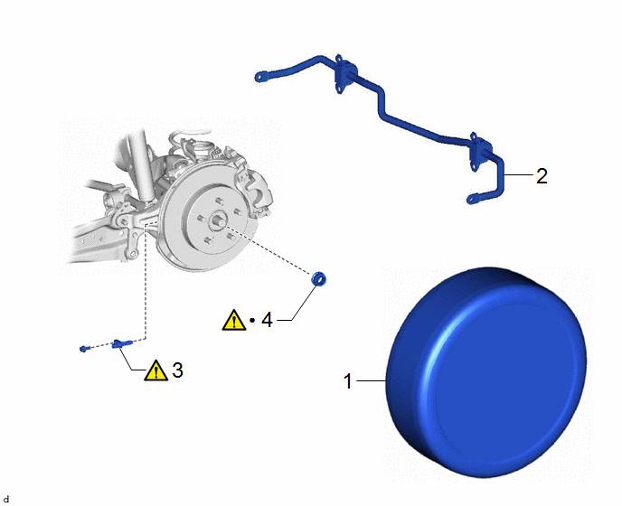
COMPONENTS (REMOVAL)
|
Procedure |
Part Name Code |
.png) |
.png) |
.png) |
|
|---|---|---|---|---|---|
|
1 |
REAR WHEELS |
- |
- |
- |
- |
|
2 |
REAR STABILIZER BAR |
48812 |
- |
- |
- |
|
3 |
REAR SKID CONTROL SENSOR |
89544E |
|
- |
- |
|
4 |
REAR AXLE SHAFT NUT |
42312B |
|
- |
- |
|
● |
Non-reusable part |
- |
- |

|
Procedure |
Part Name Code |
.png) |
.png) |
.png) |
|
|---|---|---|---|---|---|
|
5 |
REAR DRIVE SHAFT ASSEMBLY |
42340B |
|
- |
- |
CAUTION / NOTICE / HINT
HINT:
- Use the same procedure for the RH side and LH side.
- The following procedure is for the LH side.
PROCEDURE
1. REMOVE REAR WHEELS
Click here .gif)
2. REMOVE REAR STABILIZER BAR
Click here .gif)
3. REMOVE REAR SKID CONTROL SENSOR
.png) |
Click here |
4. REMOVE REAR AXLE SHAFT NUT
.png)
(1) Using SST and a hammer, release the staked part of the rear axle shaft nut.
SST: 09930-00010
NOTICE:
Loosen the staked part of the rear axle shaft nut completely, otherwise the threads of the rear drive shaft assembly may be damaged.
(2) Using a 30 mm deep socket wrench, remove the rear axle shaft nut while applying the brakes.
5. REMOVE REAR DRIVE SHAFT ASSEMBLY

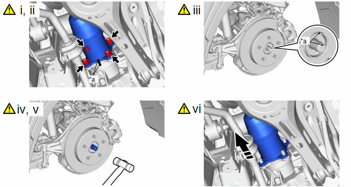
|
*a |
Matchmark |
- |
- |
.png) |
Remove in this Direction |
- |
- |
(1) Put matchmarks on the rear drive shaft assembly and differential side gear shaft sub-assembly.
(2) Remove the 4 nuts and 4 washers.
(3) Put matchmarks on the rear drive shaft assembly and the rear axle hub and bearing assembly.
(4) Using a plastic hammer, separate the rear drive shaft assembly from the rear axle hub and bearing assembly.
NOTICE:
- Do not damage the rear drive shaft outboard joint boot.
- Do not drop the rear drive shaft assembly.
(5) If it is difficult to separate the rear drive shaft assembly from the rear axle hub and bearing assembly, tap the end of the rear drive shaft assembly using a brass bar and a hammer.
(6) Push the rear drive shaft inboard joint assembly toward the outside of the vehicle and remove the rear drive shaft assembly from the differential side gear shaft sub-assembly.
NOTICE:
Do not damage the rear drive shaft inboard joint boot.


