Toyota Corolla Cross: Removal
REMOVAL
CAUTION / NOTICE / HINT
COMPONENTS (REMOVAL)
|
Procedure |
Part Name Code |
.png) |
.png) |
.png) |
|
|---|---|---|---|---|---|
|
1 |
REAR WHEEL |
- |
- |
- |
- |
|
2 |
REAR SKID CONTROL SENSOR |
89544E |
|
||
|
3 |
REAR AXLE SHAFT NUT |
42312B |
|
- |
- |
|
4 |
NO. 2 PARKING BRAKE WIRE ASSEMBLY |
890C0A |
|
- |
- |
|
5 |
REAR FLEXIBLE HOSE |
47319F |
- |
- |
- |
|
6 |
REAR DISC BRAKE CALIPER ASSEMBLY |
- |
|
- |
- |
|
7 |
REAR DISC |
42431 |
|
- |
- |
|
8 |
REAR AXLE HUB AND BEARING ASSEMBLY |
42450B |
|
- |
- |
|
*1 |
REAR DISC BRAKE DUST COVER SUB-ASSEMBLY |
- |
- |
|
● |
Non-reusable part |
- |
- |
CAUTION / NOTICE / HINT
HINT:
- Use the same procedure for the RH side and LH side.
- The following procedure is for the LH side.
PROCEDURE
1. REMOVE REAR WHEEL
Click here .gif)
2. REMOVE REAR SKID CONTROL SENSOR
.png) |
Click here |
3. REMOVE REAR AXLE SHAFT NUT
.png) |
|
4. DISCONNECT NO. 2 PARKING BRAKE WIRE ASSEMBLY
.png) |
Click here |
5. SEPARATE REAR FLEXIBLE HOSE
Click here .gif)
6. SEPARATE REAR DISC BRAKE CALIPER ASSEMBLY
.png) |
Click here |
7. REMOVE REAR DISC
.png) |
Click here |
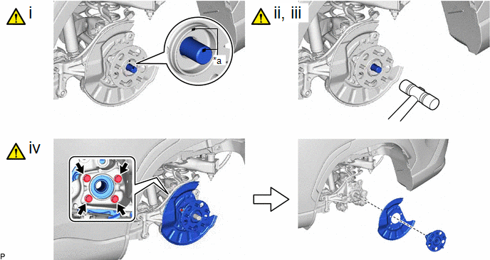
8. REMOVE REAR AXLE HUB AND BEARING ASSEMBLY

|
*a |
Matchmark |
- |
- |
(1) Put matchmarks on the rear drive shaft assembly and rear axle hub and bearing assembly.
(2) Using a plastic hammer, separate the rear drive shaft assembly from the rear axle hub and bearing assembly.
NOTICE:
- Do not damage the rear drive shaft outboard joint boot.
- Do not push the rear axle hub and bearing assembly towards the outside of the vehicle any further than necessary.
(3) If it is difficult to separate the rear drive shaft assembly from the rear axle hub and bearing assembly, tap the end of the rear drive shaft assembly using a brass bar and a hammer.
(4) Remove the 4 bolts, rear axle hub and bearing assembly and rear disc brake dust cover sub-assembly from the rear axle carrier sub-assembly.
NOTICE:
- Do not drop the rear axle hub and bearing assembly.
- Be careful not to damage the speed sensor rotor or contact surfaces.
- Do not allow foreign matter to contact the speed sensor rotor or contact surfaces.


