Toyota Corolla Cross: Rear Axle Hub Bolt (for Awd)
Components
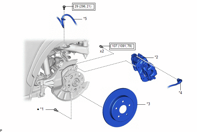
COMPONENTS
ILLUSTRATION
|
*1 |
REAR AXLE HUB BOLT |
*2 |
REAR DISC BRAKE CALIPER ASSEMBLY |
|
*3 |
REAR DISC |
*4 |
NO. 2 PARKING BRAKE WIRE ASSEMBLY |
|
*5 |
REAR FLEXIBLE HOSE |
- |
- |
.png) |
Tightening torque for "Major areas involving basic vehicle performance such as moving/turning/stopping": N*m (kgf*cm, ft.*lbf) |
● |
Non-reusable part |
Replacement
REPLACEMENT
CAUTION / NOTICE / HINT
HINT:
- Use the same procedure for the RH side and LH side.
- The following procedure is for the LH side.
PROCEDURE
1. REMOVE REAR WHEEL
Click here .gif)
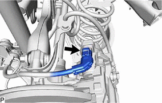
2. DISCONNECT NO. 2 PARKING BRAKE WIRE ASSEMBLY
|
(a) Disconnect the No. 2 parking brake wire assembly connector from the parking brake actuator assembly. NOTICE:
|
|
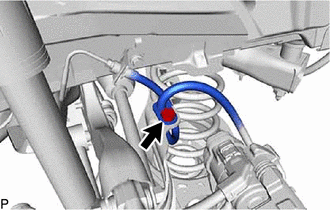
3. SEPARATE REAR FLEXIBLE HOSE
|
(a) Remove the bolt and separate the rear flexible hose from the No. 4 flexible hose bracket. |
|
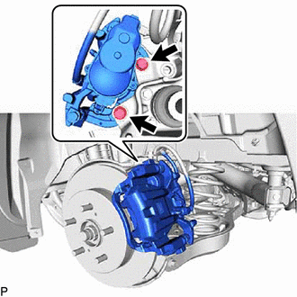
4. SEPARATE REAR DISC BRAKE CALIPER ASSEMBLY
|
(a) Remove the 2 bolts and separate the rear disc brake caliper assembly from the rear axle carrier sub-assembly. NOTICE: Use wire or an equivalent tool to keep the rear disc brake caliper assembly from hanging by the rear flexible hose. |
|
5. REMOVE REAR DISC
Click here
6. REMOVE REAR AXLE HUB BOLT
(a) Temporarily install 2 service nuts to the rear axle hub bolts as shown in the illustration.
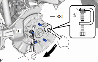
|
*a |
Service Nut |
.png) |
Turn |
Recommended Service Nut:
Thread diameter: 12.0 mm (0.472 in.)
Thread pitch: 1.5 mm (0.0591 in.)
NOTICE:
Install the service nuts to prevent damage to the rear axle hub bolts.
(b) Using SST and a screwdriver or an equivalent tool to hold the rear axle hub and bearing assembly, remove the rear axle hub bolt.
SST: 09611-12010
NOTICE:
Do not damage the threads of the rear axle hub bolts.
7. INSTALL REAR AXLE HUB BOLT
(a) Temporarily install a new rear axle hub bolt to the rear axle hub and bearing assembly.
(b) Install a washer and service nut to the rear axle hub bolt as shown in the illustration.
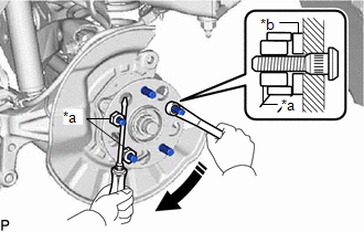
|
*a |
Service Nut |
|
*b |
Washer |
|
|
Turn |
Recommended Service Nut:
Thread diameter: 12.0 mm (0.472 in.)
Thread pitch: 1.5 mm (0.0591 in.)
HINT:
Recommended washer thickness is 5 mm (0.197 in.) or more.
(c) Using a screwdriver or an equivalent tool to hold the rear axle hub and bearing assembly, install the rear axle hub bolt by tightening the service nut.
NOTICE:
- Install the service nuts to prevent damage to the rear axle hub bolts.
- Do not damage the threads of the rear axle hub bolts.
(d) Remove the 3 service nuts and washer from the 3 rear axle hub bolts.
8. INSTALL REAR DISC
Click here
9. INSTALL REAR DISC BRAKE CALIPER ASSEMBLY
(a) Install the rear disc brake caliper assembly to the rear axle carrier sub-assembly with the 2 bolts.
Torque:
107 N·m {1091 kgf·cm, 79 ft·lbf}
NOTICE:
- Do not twist the rear flexible hose when installing the rear disc brake caliper assembly.
- Make sure that there is no foreign matter on the threads of the bolt.
10. INSTALL REAR FLEXIBLE HOSE
(a) Install the rear flexible hose to the No. 4 flexible hose bracket with the bolt.
Torque:
29 N·m {296 kgf·cm, 21 ft·lbf}
11. CONNECT NO. 2 PARKING BRAKE WIRE ASSEMBLY
(a) Connect the No. 2 parking brake wire assembly connector to the parking brake actuator assembly.
NOTICE:
- Remove any dirt or foreign matter on and around the No. 2 parking brake wire assembly connector before performing this step.
- Do not allow water, oil or dirt to enter the No. 2 parking brake wire assembly connector.
12. INSTALL REAR WHEEL
Click here


