Toyota Corolla Cross: Removal
REMOVAL
CAUTION / NOTICE / HINT
COMPONENTS (REMOVAL)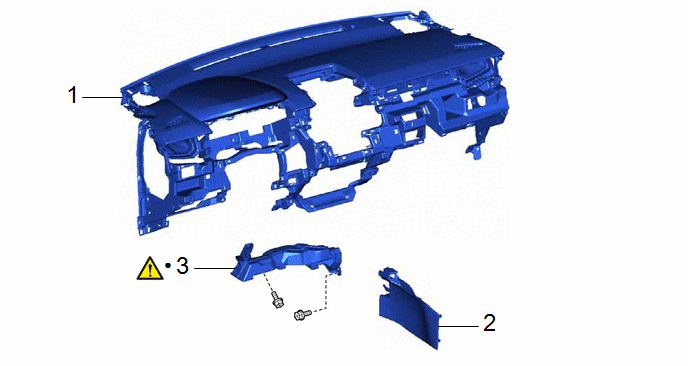
|
Procedure |
Part Name Code |
.png) |
.png) |
.png) |
|
|---|---|---|---|---|---|
|
1 |
INSTRUMENT PANEL SAFETY PAD ASSEMBLY |
55400 |
- |
- |
- |
|
2 |
FRONT NO. 1 CONSOLE BOX INSERT |
58816D |
- |
- |
- |
|
3 |
NO. 1 AIR DUCT |
87211 |
|
- |
- |
|
● |
Non-reusable part |
- |
- |
|
Procedure |
Part Name Code |
|
|
|
|
|---|---|---|---|---|---|
|
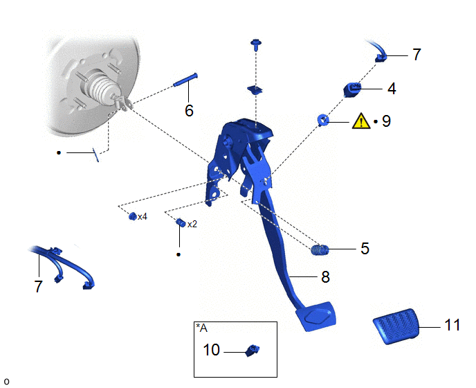
4 |
STOP LIGHT SWITCH ASSEMBLY |
84340 |
- |
- |
- |
|
5 |
BRAKE PEDAL RETURN SPRING |
47101A |
- |
- |
- |
|
6 |
PUSH ROD PIN |
47264A |
- |
- |
- |
|
7 |
WIRE HARNESS |
- |
- |
- |
- |
|
8 |
BRAKE PEDAL SUPPORT ASSEMBLY |
47110 |
- |
- |
- |
|
9 |
STOP LIGHT SWITCH MOUNTING ADJUSTER |
84345 |
|
- |
- |
|
10 |
WIRING HARNESS CONNECTOR |
82824 |
- |
- |
- |
|
11 |
BRAKE PEDAL PAD |
47121 |
- |
- |
- |
|
*A |
for 2WD |
- |
- |
|
● |
Non-reusable part |
- |
- |
CAUTION / NOTICE / HINT
The necessary procedures (adjustment, calibration, initialization, or registration) that must be performed after parts are removed, installed, or replaced during brake pedal support assembly removal/installation are shown below.
HINT:
When the cable is disconnected/reconnected to the auxiliary battery terminal, systems temporarily stop operating. However, each system has a function that completes learning the first time the system is used.
- Learning completes when vehicle is driven
Effect/Inoperative Function When Necessary Procedures are not Performed
Necessary Procedures
Link
Front camera system
Drive the vehicle straight ahead at 15 km/h (10 mph) or more for 1 second or more.
.gif)
Stop and start system
Drive the vehicle until stop and start control is permitted (approximately 5 to 60 minutes)
- Learning completes when vehicle is operated normally
Effect/Inoperative Function When Necessary Procedures are not Performed
Necessary Procedures
Link
Power door lock control system
- Back door opener
Perform door unlock operation with door control switch or electrical key transmitter sub-assembly switch.
Power back door system
Fully close the back door by hand.
HINT:
Initialization is not necessary if the above procedures are performed while the back door is closed.
Air conditioning system
After the ignition switch is turned to ON, the servo motor standard position is recognized.
-
PROCEDURE
1. REMOVE INSTRUMENT PANEL SAFETY PAD ASSEMBLY
Click here
2. REMOVE FRONT NO. 1 CONSOLE BOX INSERT
Click here
3. REMOVE NO. 1 AIR DUCT
|
|
Click here |
4. REMOVE STOP LIGHT SWITCH ASSEMBLY
Click here
5. REMOVE BRAKE PEDAL RETURN SPRING

6. REMOVE PUSH ROD PIN

7. SEPARATE WIRE HARNESS
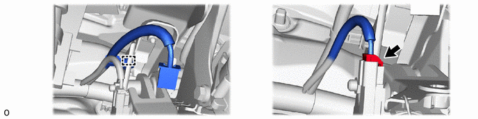
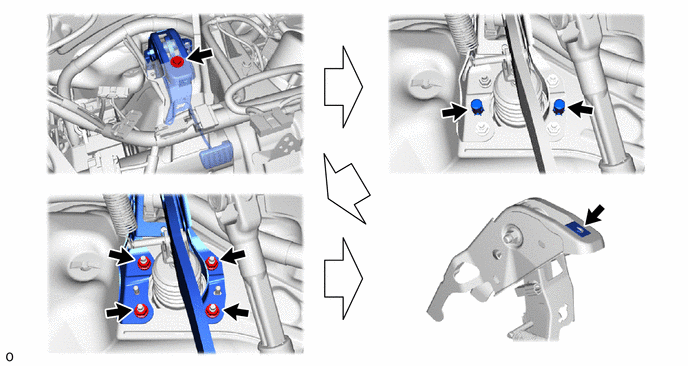
8. REMOVE BRAKE PEDAL SUPPORT ASSEMBLY
9. REMOVE STOP LIGHT SWITCH MOUNTING ADJUSTER
|
|
Click here |
10. REMOVE WIRING HARNESS CONNECTOR (for 2WD)

11. REMOVE BRAKE PEDAL PAD