Toyota Corolla Cross: Removal
REMOVAL
CAUTION / NOTICE / HINT
COMPONENTS (REMOVAL)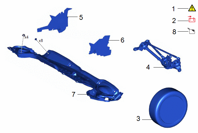
|
Procedure |
Part Name Code |
.png) |
.png) |
.png) |
|
|---|---|---|---|---|---|
|
1 |
PRECAUTION |
- |
|
- |
- |
|
2 |
DISCONNECT CABLE FROM NEGATIVE AUXILIARY BATTERY TERMINAL |
- |
- |
- |
- |
|
3 |
FRONT WHEEL LH |
- |
- |
- |
- |
|
4 |
WINDSHIELD WIPER MOTOR AND LINK ASSEMBLY |
- |
- |
- |
- |
|
5 |
NO. 1 HEATER AIR DUCT SPLASH SHIELD SEAL |
55737B |
- |
- |
- |
|
6 |
WATER GUARD PLATE |
55734D |
- |
- |
- |
|
7 |
OUTER COWL TOP PANEL SUB-ASSEMBLY |
55701J |
- |
- |
- |
|
8 |
BRAKE FLUID |
- |
- |
|
- |
|
Procedure |
Part Name Code |
|
|
|
|
|---|---|---|---|---|---|
|
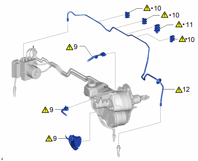
9 |
ENGINE ROOM MAIN WIRE |
82111 |
|
- |
- |
|
10 |
NO. 3 BRAKE TUBE CLAMP |
47373B |
|
- |
- |
|
11 |
NO. 4 BRAKE TUBE CLAMP |
47374B |
|
- |
- |
|
12 |
FRONT NO. 5 BRAKE TUBE |
47315 |
|
- |
- |
|
● |
Non-reusable part |
- |
- |
|
Procedure |
Part Name Code |
|
|
|
|
|---|---|---|---|---|---|
|
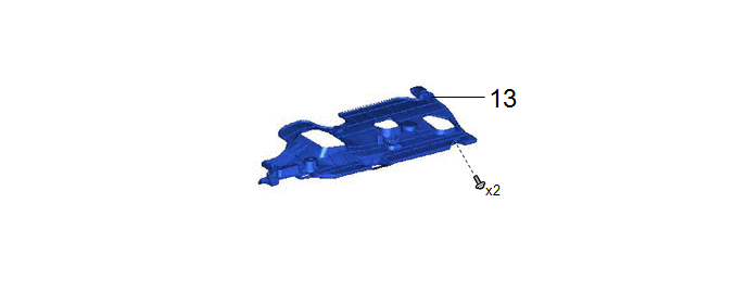
13 |
NO. 1 INSTRUMENT PANEL UNDER COVER SUB-ASSEMBLY |
55606 |
- |
- |
- |
|
Procedure |
Part Name Code |
|
|
|
|
|---|---|---|---|---|---|
|
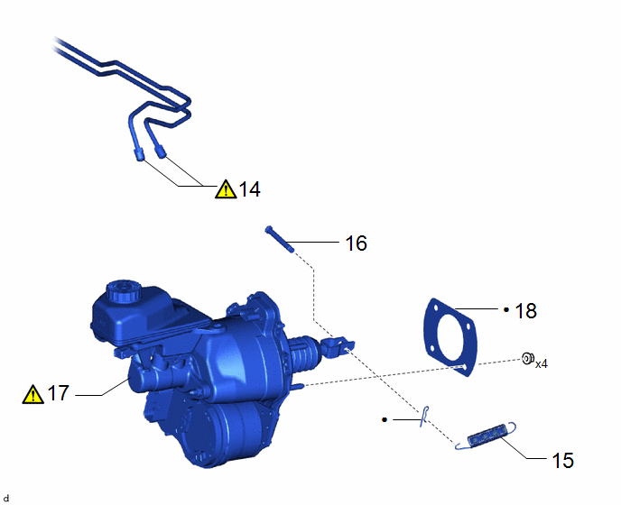
14 |
SEPARATE BRAKE LINE |
- |
|
- |
- |
|
15 |
BRAKE PEDAL RETURN SPRING |
47101A |
- |
- |
- |
|
16 |
PUSH ROD PIN |
47264A |
- |
- |
- |
|
17 |
BRAKE BOOSTER WITH MASTER CYLINDER ASSEMBLY |
47210L |
|
- |
- |
|
18 |
BRAKE BOOSTER GASKET |
44785 |
- |
- |
- |
|
● |
Non-reusable part |
- |
- |
CAUTION / NOTICE / HINT
The necessary procedures (adjustment, calibration, initialization, or registration) that must be performed after parts are removed, installed, or replaced during brake booster with master cylinder assembly removal/installation are shown below.
Necessary Procedures After Parts Removed/Installed/Replaced|
Replaced Part or Performed Procedure |
Necessary Procedure |
Effect/Inoperative Function when Necessary Procedure not Performed |
Link |
|---|---|---|---|
| *1: Even when not replacing the part, it is necessary to perform the specified necessary procedures after installation. | |||
|
Electric brake booster (brake booster with master cylinder assembly) |
Update ECU security key (Only necessary after replacement) |
Vehicle Control History (RoB) are stored |
|
|
|
|
|
HINT:
When the cable is disconnected/reconnected to the auxiliary battery terminal, systems temporarily stop operating. However, each system has a function that completes learning the first time the system is used.
- Learning completes when vehicle is driven
Effect/Inoperative Function When Necessary Procedures are not Performed
Necessary Procedures
Link
Front camera system
Drive the vehicle straight ahead at 15 km/h (10 mph) or more for 1 second or more.
.gif)
- Learning completes when vehicle is operated normally
Effect/Inoperative Function When Necessary Procedures are not Performed
Necessary Procedures
Link
Power door lock control system
- Back door opener
Perform door unlock operation with door control switch or electrical key transmitter sub-assembly switch.
Power back door system
Fully close the back door by hand.
HINT:
Initialization is not necessary if the above procedures are performed while the back door is closed.
Air conditioning system
After the ignition switch is turned to ON, the servo motor standard position is recognized.
-
PROCEDURE
1. PRECAUTION
|
|
NOTICE: After the ignition switch is turned off, there may be a waiting time before disconnecting the negative (-) auxiliary battery terminal. Click here |
2. DISCONNECT CABLE FROM NEGATIVE AUXILIARY BATTERY TERMINAL
Click here
3. REMOVE FRONT WHEEL LH
Click here
4. REMOVE WINDSHIELD WIPER MOTOR AND LINK ASSEMBLY
Click here
5. REMOVE NO. 1 HEATER AIR DUCT SPLASH SHIELD SEAL
Click here
6. REMOVE WATER GUARD PLATE
Click here
7. REMOVE OUTER COWL TOP PANEL SUB-ASSEMBLY
Click here
8. DRAIN BRAKE FLUID
|
|
NOTICE: If brake fluid leaks onto any painted surface, immediately wash it off. |
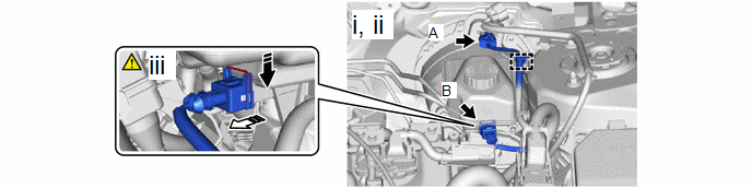
9. SEPARATE ENGINE ROOM MAIN WIRE
.png) |
Push in this direction |
.png) |
Disconnect the connector in this direction |
(1) Disconnect the connector (A) from the brake booster.
(2) Disengage the clamp from the brake master cylinder reservoir assembly.
(3) Disconnect the connector (B) from the brake master cylinder reservoir assembly as shown inthe illustration.
|
|
Pressing the lock |
|
Lift the lock lever |
 |
Disconnect the connector |
- |
- |
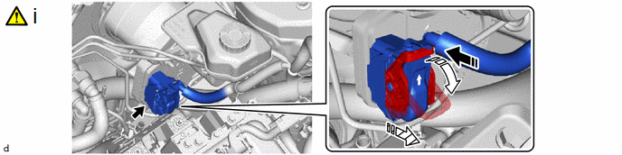
(1) As shown in the illustration, lift the lock lever while pressing the lock and disconnect the connector from the brake booster.
NOTICE:
Be careful not to allow any brake fluid to enter the connector.
10. REMOVE NO. 3 BRAKE TUBE CLAMP
|
|
NOTICE:
|
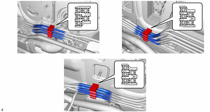
11. REMOVE NO. 4 BRAKE TUBE CLAMP
|
|
NOTICE:
|

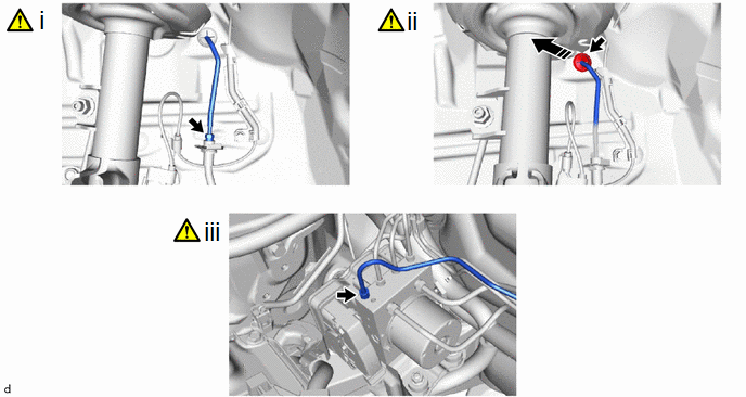
12. SEPARATE FRONT NO. 5 BRAKE TUBE
|
|
NOTICE:
|
|
|
Disconnect in this Direction |
- |
- |
(1) Using a union nut wrench, disconnect the front No. 5 brake tube from the front flexible hose LH.
(2) Disconnect the front brake tube grommet from the vehicle body as shown in the illustration.
(3) Using a union nut wrench, disconnect the front No. 5 brake tube from the brake actuator assembly.
13. REMOVE NO. 1 INSTRUMENT PANEL UNDER COVER SUB-ASSEMBLY
Click here
14. SEPARATE BRAKE LINE
|
|
NOTICE:
|

(1) Using a union nut wrench, disconnect the 2 brake lines from the brake master cylinder sub-assembly.
15. REMOVE BRAKE PEDAL RETURN SPRING
Click here
16. REMOVE PUSH ROD PIN
Click here
17. REMOVE BRAKE BOOSTER WITH MASTER CYLINDER ASSEMBLY
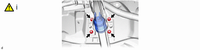
(1) Remove the 4 nuts and brake booster with master cylinder assembly.
NOTICE:
- Do not kink or damage the brake lines.

Do not carry the brake booster with master cylinder assembly by the parts shown in the illustration.*a
Connectors
*b
Boot
*c
Brake Master Cylinder Push Rod Clevis
*d
Brake Master Cylinder Reservoir Assembly
- Be careful not to allow any brake fluid to enter the connector.
18. REMOVE BRAKE BOOSTER GASKET