Toyota Corolla Cross: Removal
REMOVAL
CAUTION / NOTICE / HINT
COMPONENTS (REMOVAL)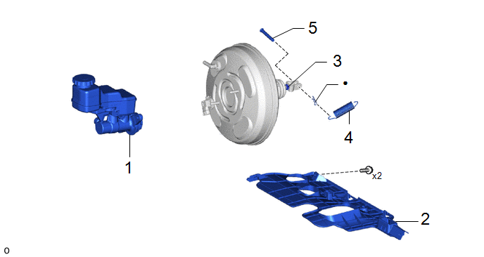
|
Procedure |
Part Name Code |
.png) |
.png) |
.png) |
|
|---|---|---|---|---|---|
|
1 |
BRAKE MASTER CYLINDER SUB-ASSEMBLY |
47201 |
- |
- |
- |
|
2 |
NO. 1 INSTRUMENT PANEL UNDER COVER SUB-ASSEMBLY |
55606 |
- |
- |
- |
|
3 |
LOOSEN CLEVIS LOCK NUT |
- |
- |
- |
- |
|
4 |
BRAKE PEDAL RETURN SPRING |
47101A |
- |
- |
- |
|
5 |
PUSH ROD PIN |
47264A |
- |
- |
- |
|
● |
Non-reusable part |
- |
- |

|
Procedure |
Part Name Code |
|
|
|
|
|---|---|---|---|---|---|
|
6 |
NO. 1 ENGINE UNDER COVER ASSEMBLY |
51410 |
- |
- |
- |
|
7 |
DASH PANEL HEAT INSULATOR |
55225C |
- |
- |
- |
|
Procedure |
Part Name Code |
|
|
|
|
|---|---|---|---|---|---|
|
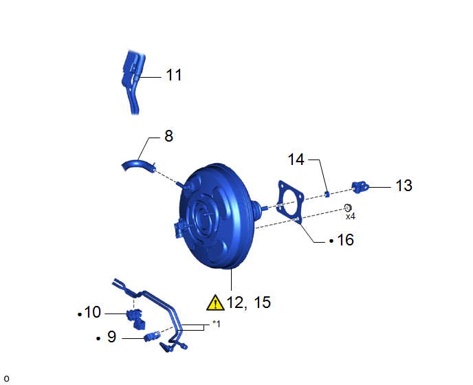
8 |
CHECK VALVE TO CONNECTOR TUBE HOSE |
- |
- |
- |
- |
|
9 |
NO. 5 BRAKE TUBE CLAMP |
47375 |
- |
- |
- |
|
10 |
NO. 4 BRAKE TUBE CLAMP |
47374B |
- |
- |
- |
|
11 |
FUEL TUBE |
- |
- |
- |
- |
|
12 |
SEPARATE BRAKE BOOSTER ASSEMBLY |
44610 |
|
- |
- |
|
13 |
BRAKE MASTER CYLINDER PUSH ROD CLEVIS |
- |
- |
- |
- |
|
14 |
REMOVE CLEVIS LOCK NUT |
- |
- |
- |
- |
|
15 |
REMOVE BRAKE BOOSTER ASSEMBLY |
44610 |
|
- |
- |
|
16 |
BRAKE BOOSTER GASKET |
44785 |
- |
- |
- |
|
*1 |
BRAKE LINE |
- |
- |
|
● |
Non-reusable part |
- |
- |
CAUTION / NOTICE / HINT
The necessary procedures (adjustment, calibration, initialization, or registration) that must be performed after parts are removed, installed, or replaced during the brake booster assembly removal/installation are shown below.
HINT:
When the cable is disconnected/reconnected to the auxiliary battery terminal, systems temporarily stop operating. However, each system has a function that completes learning the first time the system is used.
- Learning completes when vehicle is driven
Effect/Inoperative Function When Necessary Procedures are not Performed
Necessary Procedures
Link
Front camera system
Drive the vehicle straight ahead at 15 km/h (10 mph) or more for 1 second or more.
.gif)
Stop and start system
Drive the vehicle until stop and start control is permitted (approximately 5 to 60 minutes)
- Learning completes when vehicle is operated normally
Effect/Inoperative Function When Necessary Procedures are not Performed
Necessary Procedures
Link
Power door lock control system
- Back door opener
Perform door unlock operation with door control switch or electrical key transmitter sub-assembly switch.
Power back door system
Fully close the back door by hand.
HINT:
Initialization is not necessary if the above procedures are performed while the back door is closed.
Air conditioning system
After the ignition switch is turned to ON, the servo motor standard position is recognized.
-
PROCEDURE
1. REMOVE BRAKE MASTER CYLINDER SUB-ASSEMBLY
Click here
2. REMOVE NO. 1 INSTRUMENT PANEL UNDER COVER SUB-ASSEMBLY
Click here
3. LOOSEN CLEVIS LOCK NUT

|
*1 |
Lock Nut |
*2 |
Brake Master Cylinder Push Rod Clevis |
4. REMOVE BRAKE PEDAL RETURN SPRING
Click here
5. REMOVE PUSH ROD PIN
Click here
6. REMOVE NO. 1 ENGINE UNDER COVER ASSEMBLY
Click here
7. REMOVE DASH PANEL HEAT INSULATOR

8. DISCONNECT CHECK VALVE TO CONNECTOR TUBE HOSE

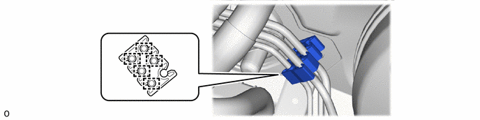
9. REMOVE NO. 5 BRAKE TUBE CLAMP
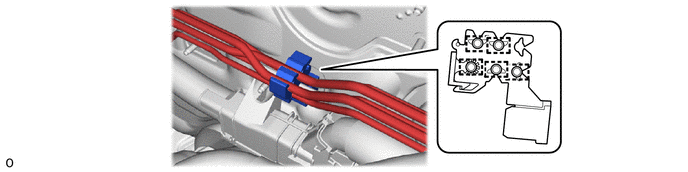
10. REMOVE NO. 4 BRAKE TUBE CLAMP
11. SEPARATE FUEL TUBE

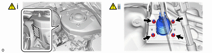
12. SEPARATE BRAKE BOOSTER ASSEMBLY
.png) |
Protective Tape |
- |
- |
(1) Apply protective tape around the vehicle body.
(2) Remove the 4 nuts and push the brake booster assembly toward the engine compartment.
NOTICE:
Do not apply excessive force to the brake lines.
13. REMOVE BRAKE MASTER CYLINDER PUSH ROD CLEVIS

14. REMOVE CLEVIS LOCK NUT

15. REMOVE BRAKE BOOSTER ASSEMBLY

(1) Remove the brake booster assembly from the vehicle body.
NOTICE:
Do not apply excessive force to the brake lines.
16. REMOVE BRAKE BOOSTER GASKET