Toyota Corolla Cross: Rear Door Courtesy Switch Circuit
DESCRIPTION
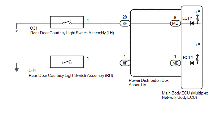
The main body ECU (multiplex network body ECU) detects the condition of the rear door courtesy light switch assembly.
WIRING DIAGRAM
CAUTION / NOTICE / HINT
NOTICE:
Before replacing the main body ECU (multiplex network body ECU), refer to Registration.*1
for HEV Model: Click here .gif)
for Gasoline Model: Click here
- *1: w/ Smart Key System
PROCEDURE
|
1. | READ VALUE USING GTS |
(a) Read the Data List according to the display on the GTS.
Body Electrical > Main Body > Data List|
Tester Display | Measurement Item |
Range | Normal Condition |
Diagnostic Note |
|---|---|---|---|---|
|
RR Door Courtesy Switch Status |
Rear door courtesy light switch assembly (RH) signal |
CLOSE or OPEN | CLOSE: Rear door RH closed OPEN: Rear door RH open |
- |
| RL Door Courtesy Switch Status |
Rear door courtesy light switch assembly (LH) signal |
CLOSE or OPEN | CLOSE: Rear door LH closed OPEN: Rear door LH open |
- |
|
Tester Display |
|---|
| RR Door Courtesy Switch Status |
|
RL Door Courtesy Switch Status |
OK:
Normal conditions listed above are displayed.
|
Result | Proceed to |
|---|---|
|
OK | A |
|
NG ("RL Door Courtesy Switch Status" is not normal) |
B |
| NG ("RR Door Courtesy Switch Status" is not normal) |
C |
| A |
.gif) | PROCEED TO NEXT SUSPECTED AREA SHOWN IN PROBLEM SYMPTOMS TABLE |
| C |
| GO TO STEP 5 |
|
.gif)
| 2. |
INSPECT REAR DOOR COURTESY LIGHT SWITCH ASSEMBLY (LH) |
Click here
| NG | | REPLACE REAR DOOR COURTESY LIGHT SWITCH ASSEMBLY LH |
|
| 3. |
CHECK HARNESS AND CONNECTOR (REAR DOOR COURTESY LIGHT SWITCH ASSEMBLY (LH) - POWER DISTRIBUTION BOX ASSEMBLY) |
(a) Disconnect the 8F power distribution box assembly connector.
(b) Measure the resistance according to the value(s) in the table below.
Standard Resistance:
|
Tester Connection | Condition |
Specified Condition |
|---|---|---|
|
O31-1 - 8F-28 | Always |
Below 1 Ω |
|
O31-1 - Body ground | Always |
10 kΩ or higher |
|
8F-28 - Body ground | Always |
10 kΩ or higher |
| NG | | REPAIR OR REPLACE HARNESS OR CONNECTOR |
|
| 4. |
INSPECT POWER DISTRIBUTION BOX ASSEMBLY |
|
*a | Component without harness connected (Power Distribution Box Assembly) |
- | - |
(a) Remove the main body ECU (multiplex network body ECU) from the power distribution box assembly.
Click here
(b) Measure the resistance according to the value(s) in the table below.
Standard Resistance:
|
Tester Connection | Condition |
Specified Condition |
|---|---|---|
|
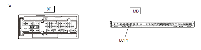
8F-28 - MB-6 (LCTY) | Always |
Below 1 Ω |
| OK | | REPLACE MAIN BODY ECU (MULTIPLEX NETWORK BODY ECU) |
| NG | | REPLACE POWER DISTRIBUTION BOX ASSEMBLY |
| 5. |
INSPECT REAR DOOR COURTESY LIGHT SWITCH ASSEMBLY (RH) |
Click here
| NG | | REPLACE REAR DOOR COURTESY LIGHT SWITCH ASSEMBLY (RH) |
|
| 6. |
CHECK HARNESS AND CONNECTOR (REAR DOOR COURTESY LIGHT SWITCH ASSEMBLY (RH) - POWER DISTRIBUTION BOX ASSEMBLY) |
(a) Disconnect the 8F power distribution box assembly connector.
(b) Measure the resistance according to the value(s) in the table below.
Standard Resistance:
|
Tester Connection | Condition |
Specified Condition |
|---|---|---|
|
O34-1 - 8F-1 | Always |
Below 1 Ω |
|
O34-1 - Body ground | Always |
10 kΩ or higher |
|
8F-1 - Body ground | Always |
10 kΩ or higher |
| NG | | REPAIR OR REPLACE HARNESS OR CONNECTOR |
|
| 7. |
INSPECT POWER DISTRIBUTION BOX ASSEMBLY |
|
*a | Component without harness connected (Power Distribution Box Assembly) |
- | - |
(a) Remove the main body ECU (multiplex network body ECU) from the power distribution box assembly.
Click here
(b) Measure the resistance according to the value(s) in the table below.
Standard Resistance:
|
Tester Connection | Condition |
Specified Condition |
|---|---|---|
|
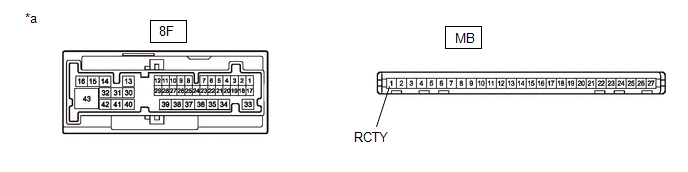
8F-1 - MB-1 (RCTY) | Always |
Below 1 Ω |
| OK | | REPLACE MAIN BODY ECU (MULTIPLEX NETWORK BODY ECU) |
| NG | | REPLACE POWER DISTRIBUTION BOX ASSEMBLY |


