Toyota Corolla Cross: Interior Light Circuit
DESCRIPTION
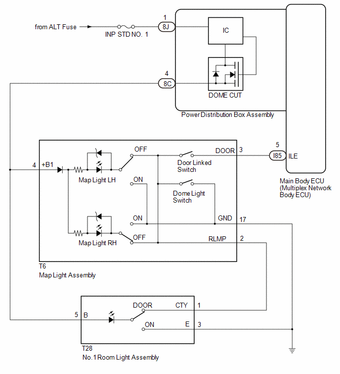
The main body ECU (multiplex network body ECU) controls the operation of the following lights:
- Map Light Assembly
- Room Light Assembly
WIRING DIAGRAM
CAUTION / NOTICE / HINT
NOTICE:
- Inspect the fuses for circuits related to this system before performing the following procedure.
- Before replacing the main body ECU (multiplex network body ECU), refer to Registration.*1
for HEV Model: Click here
.gif)
for Gasoline Model: Click here
- *1: w/ Smart Key System
HINT:
The DOME CUT relay supplies power to the interior lights. If all the lights that use power from the DOME CUT relay do not turn on, check the interior light auto cut circuit first.
Click here
PROCEDURE
| 1. |
PERFORM ACTIVE TEST USING GTS |
(a) Perform the Active Test according to the display on the GTS.
Body Electrical > Main Body > Active Test|
Tester Display | Measurement Item |
Control Range | Diagnostic Note |
|---|---|---|---|
|
Illuminated Entry System |
Turns on the lights that are controlled by the illuminated entry system*1 |
OFF or ON | Perform the Active Test with DOOR switch in the map light assembly and room light assembly turned on. |
- *1: Refer to System Description for the lights that are controlled by the illuminated entry system.
Click here
|
Tester Display |
|---|
| Illuminated Entry System |
OK:
All lights that are controlled by the illuminated entry system come on.
|
Result | Proceed to |
|---|---|
|
OK | A |
|
NG (Map light does not come on) |
B |
| NG (Room light does not come on) |
C |
| NG (Map light and room light does not come on) |
D |
| A |
.gif) | PROCEED TO NEXT SUSPECTED AREA SHOWN IN PROBLEM SYMPTOMS TABLE |
| C |
| GO TO STEP 4 |
| D |
| GO TO STEP 7 |
|
.gif)
| 2. |
INSPECT MAP LIGHT ASSEMBLY |
Click here
| NG | |
REPLACE MAP LIGHT ASSEMBLY |
|
| 3. |
CHECK HARNESS AND CONNECTOR (MAP LIGHT ASSEMBLY - POWER DISTRIBUTION BOX ASSEMBLY) |
(a) Disconnect the 8C power distribution box assembly connector.
(b) Measure the resistance according to the value(s) in the table below.
Standard Resistance:
|
Tester Connection | Condition |
Specified Condition |
|---|---|---|
|
T6-4 (+B1) - 8C-4 | Always |
Below 1 Ω |
|
T6-4 (+B1) or 8C-4 - Body ground |
Always | 10 kΩ or higher |
| OK | | USE SIMULATION METHOD TO CHECK |
| NG | | REPAIR OR REPLACE HARNESS OR CONNECTOR |
| 4. |
INSPECT NO. 1 ROOM LIGHT ASSMEBLY |
Click here
| NG | |
REPLACE NO. 1 ROOM LIGHT ASSEMBLY |
|
| 5. |
CHECK HARNESS AND CONNECTOR (MAP LIGHT ASSEMBLY - NO. 1 ROOM LIGHT ASSEMBLY) |
(a) Disconnect the T6 map light assembly connector.
(b) Measure the resistance according to the value(s) in the table below.
Standard Resistance:
|
Tester Connection | Condition |
Specified Condition |
|---|---|---|
|
T6-4 (+B1) - T28-5 (B) |
Always | Below 1 Ω |
|
T6-2 (RLMP) - T28-1 (CTY) |
Always | Below 1 Ω |
| NG | | REPAIR OR REPLACE HARNESS OR CONNECTOR |
|
| 6. |
INSPECT MAP LIGHT ASSEMBLY |
Click here
| OK | |
USE SIMULATION METHOD TO CHECK |
| NG | | REPLACE MAP LIGHT ASSEMBLY |
| 7. |
INSPECT MAP LIGHT ASSEMBLY |
Click here
| NG | |
REPLACE MAP LIGHT ASSEMBLY |
|
| 8. |
CHECK HARNESS AND CONNECTOR (MAP LIGHT ASSEMBLY - POWER DISTRIBUTION BOX ASSEMBLY) |
(a) Disconnect the 8C power distribution box assembly connector.
(b) Disconnect the I85 main body ECU (multiplex network body ECU) connector.
(c) Measure the resistance according to the value(s) in the table below.
Standard Resistance:
|
Tester Connection | Condition |
Specified Condition |
|---|---|---|
|
T6-4(+B1) - 8C-4 | Always |
Below 1 Ω |
|
T6-3 (DOOR) - I85-5 (ILE) |
Always | Below 1 Ω |
|
T6-4 (+B1) - Body ground |
Always | 10 kΩ or higher |
|
8C-4 - Body ground | Always |
10 kΩ or higher |
|
T6-3 (DOOR) - Body ground |
Always | 10 kΩ or higher |
|
I85-5 (ILE) - Body ground |
Always | 10 kΩ or higher |
| OK | | REPLACE MAIN BODY ECU (MULTIPLEX NETWORK BODY ECU) |
| NG | | REPAIR OR REPLACE HARNESS OR CONNECTOR |


