Toyota Corolla Cross: Precaution
PRECAUTION
CHARGING SYSTEM PRECAUTION
CAUTION:
- This vehicle contains high voltage circuits standardized with orange colored
wiring and connectors, so follow the instructions in this manual to perform
the procedures correctly.
Click here
.gif)
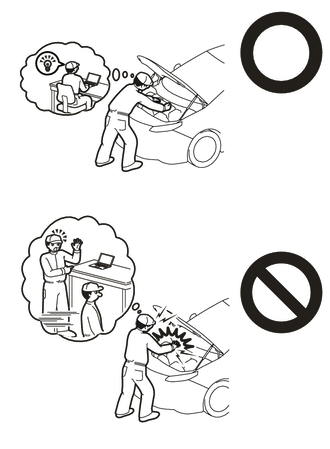
- If the correct procedures are not followed according to the instructions in this manual, there is a danger of electric shock from the high voltage circuits.
- Be sure to wear insulating gloves when working on high voltage wiring or
components.
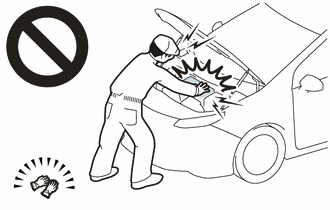
- If work is performed without wearing insulating gloves, there is a danger of electric shock.
NOTICE:
- If the auxiliary battery is fully depleted or the READY indicator does not illuminate, recharge the auxiliary battery.
- Never disconnect the auxiliary battery while the ignition switch is on (READY).
- Before giving the auxiliary battery a quick charge, disconnect the auxiliary battery cables.
- Check the auxiliary battery again before the vehicle is returned to the customer.
- When replacing the auxiliary battery, use a new auxiliary battery of the same dimensions and same capacity or more from the same class at a 20-hour rate.


