Toyota Corolla Cross: Parts Location
PARTS LOCATION
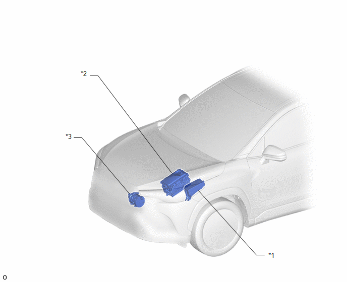
ILLUSTRATION
|
*1 |
NO. 1 ENGINE ROOM RELAY BLOCK - IGCT-MAIN NO. 1 RELAY |
*2 |
INVERTER WITH CONVERTER ASSEMBLY |
|
*3 |
COMPRESSOR WITH MOTOR ASSEMBLY |
- |
- |
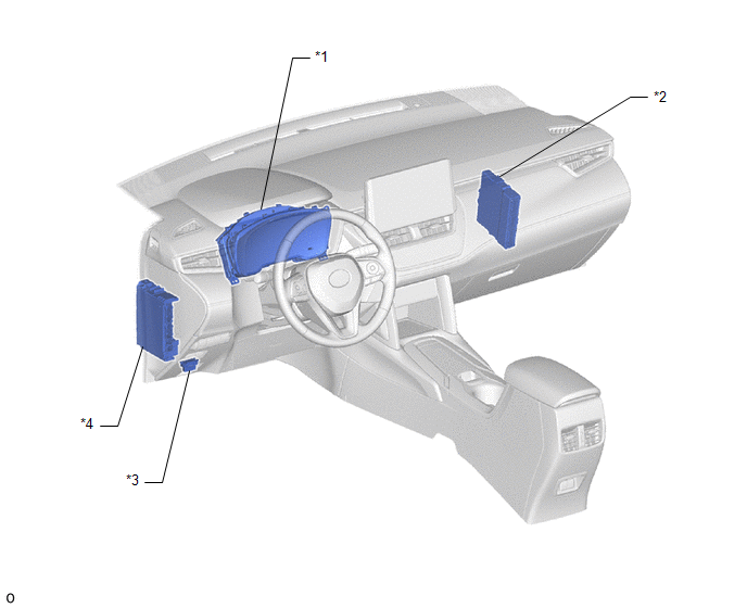
ILLUSTRATION
|
*1 |
COMBINATION METER ASSEMBLY |
*2 |
HYBRID VEHICLE CONTROL ECU |
|
*3 |
DLC3 |
*4 |
INSTRUMENT PANEL JUNCTION BLOCK ASSEMBLY - ECU-B NO. 2 |
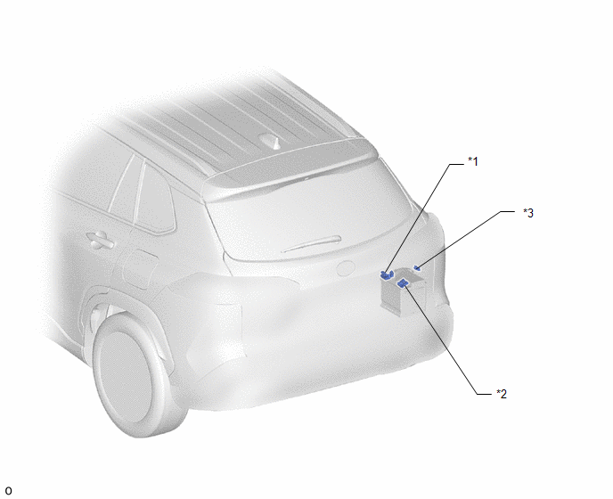
ILLUSTRATION
|
*1 |
BATTERY STATE SENSOR ASSEMBLY |
*2 |
FUSIBLE LINK BLOCK ASSEMBLY - R/B-B RR FUSE |
|
*3 |
FUSE BLOCK ASSEMBLY - BATT-S FUSE |
- |
- |


