Toyota Corolla Cross: Power Source Mode does not Change to ON (READY)
DESCRIPTION
When the electrical key transmitter sub-assembly is in the cabin and the power switch is pressed, the certification ECU (smart key ECU assembly) receives a signal and changes the power source mode. Additionally, when the shift position is in P and the brake pedal is depressed, the hybrid control system can be started by pressing the power switch. If the steering is unlocked, the hybrid control system can also be started by pressing the power switch with the shift position in P and the brake pedal depressed.
Related Data List and Active Test Items|
Problem Symptom | Data List and Active Test |
|---|---|
|
Power source mode does not change to ON (READY) | Power Source Control
|
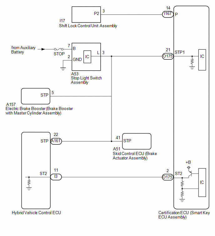
WIRING DIAGRAM
CAUTION / NOTICE / HINT
NOTICE:
- When using the GTS with the ignition switch off, connect the GTS to the DLC3 and turn a courtesy light switch on and off at intervals of 1.5 seconds or less until communication between the GTS and the vehicle begins.
Then select Model Code "KEY REGIST" under manual mode and enter the following menus: Body Electrical / Start Key(CAN). While using the GTS, periodically turn a courtesy light switch on and off at intervals of 1.5 seconds or less to maintain communication between the GTS and the vehicle.
- The smart key system (for Start Function) uses the LIN communication system and CAN communication system. Inspect the communication function by following How to Proceed with Troubleshooting. Troubleshoot the smart key system (for Start Function) after confirming that the communication systems are functioning properly.
Click here
.gif)
- If the smart key system (for Start Function) has been canceled, enable the system before performing troubleshooting.
Click here
- Inspect the fuses for circuits related to this system before performing the following procedure.
- Before replacing the certification ECU (smart key ECU assembly) or electrical key transmitter sub-assembly, refer to Registration.
Click here
- After completing repairs, confirm that the problem does not recur.
- After repair, confirm that no DTCs are output by performing "DTC Output Confirmation Operation".
PROCEDURE
|
1. | CHECK POWER SWITCH CONDITION |
(a) Get into the vehicle while carrying an electrical key transmitter sub-assembly.
(b) Move the shift position to P.
(c) With the brake pedal released, check that pressing the power switch causes the power source mode to change.
|
Result | Proceed to |
|---|---|
|
Power source mode changes : Off → ACC → ON → off |
A |
| Power source mode does not change to ACC or ON |
B |
| Power source mode changes to ON but not to ACC |
C |
| Power source mode changes to ACC but not to ON |
D |
| B |
.gif) | GO TO OTHER PROBLEM (Power Source Mode does not Change to ON (IG and ACC)) |
| C |
| GO TO OTHER PROBLEM (Power Source Mode does not Change to ON (ACC)) |
| D |
| GO TO OTHER PROBLEM (Power Source Mode does not Change to ON (IG)) |
|
.gif)
| 2. |
READ VALUE USING GTS (STOP LIGHT SWITCH) |
(a) Read the Data List according to the display on the GTS.
Body Electrical > Power Source Control > Data List|
Tester Display | Measurement Item |
Range | Normal Condition |
Diagnostic Note |
|---|---|---|---|---|
|
Stop Light Switch | State of brake pedal |
OFF or ON | OFF: Brake pedal released ON: Brake pedal depressed |
|
|
Tester Display |
|---|
| Stop Light Switch |
OK:
The GTS display changes correctly in response to the brake pedal operation.
| NG | | GO TO STEP 10 |
|
| 3. |
READ VALUE USING GTS (SHIFT P SIGNAL) |
(a) Read the Data List according to the display on the GTS.
Body Electrical > Power Source Control > Data List|
Tester Display | Measurement Item |
Range | Normal Condition |
Diagnostic Note |
|---|---|---|---|---|
|
Shift P Signal | Shift position P |
OFF or ON | OFF: Shift position not in P ON: Shift position in P |
Use this item to determine if the shift position switch is malfunctioning. |
|
Tester Display |
|---|
| Shift P Signal |
OK:
The GTS display changes correctly in response to the shift position.
| NG | | GO TO STEP 8 |
|
| 4. |
READ VALUE USING GTS (POWER SUPPLY CONDITION) |
(a) Read the Data List according to the display on the GTS.
Body Electrical > Power Source Control > Data List|
Tester Display | Measurement Item |
Range | Normal Condition |
Diagnostic Note |
|---|---|---|---|---|
|
Power Supply Condition |
Power supply state | OFF, ACC ON, IGR ON, IGP ON or Starter ON |
OFF: Ignition switch off ACC ON: Ignition switch ACC IGR ON: Ignition switch ON IGP ON: Ignition switch ON Starter ON: Sending hybrid control system start request signal |
- |
|
Tester Display |
|---|
| Power Supply Condition |
NOTICE:
Check that the key indicator display is displayed on the multi-information display in the combination meter assembly, and then press the power switch.
OK:
The GTS display changes correctly in response to the power switch operation.
| NG | | GO TO STEP 7 |
|
| 5. |
CHECK HARNESS AND CONNECTOR (CERTIFICATION ECU (SMART KEY ECU ASSEMBLY) - HYBRID VEHICLE CONTROL ECU) |
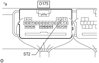
(a) Disconnect the O175 certification ECU (smart key ECU assembly) connector.
(b) Disconnect the I3 hybrid vehicle control ECU connector.
(c) Measure the resistance according to the value(s) in the table below.
Standard Resistance:
|
Tester Connection | Condition |
Specified Condition |
|---|---|---|
|
O175-2 (ST2) - I3-11 (ST2) |
Always | Below 1 Ω |
|
O175-2 (ST2) or I3-11 (ST2) - Other terminals and body ground |
Always | 10 kΩ or higher |
| NG | | REPAIR OR REPLACE HARNESS OR CONNECTOR |
|
| 6. |
CHECK CERTIFICATION ECU (SMART KEY ECU ASSEMBLY) |
(a) Connect the O175 certification ECU (smart key ECU assembly) connector.
(b) Connect the I3 hybrid vehicle control ECU connector.
| (c) Measure the voltage according to the value(s) in the table below. Standard Voltage:
|
|
| OK | | GO TO HYBRID CONTROL SYSTEM |
| NG | | REPLACE CERTIFICATION ECU (SMART KEY ECU ASSEMBLY) |
| 7. |
CHECK SECURITY INDICATOR LIGHT (IMMOBILISER FUNCTION UNSET) |
(a) Get into the vehicle while carrying an electrical key transmitter sub-assembly.
(b) Move the shift position to P.
(c) Press the power switch with the brake pedal released and check that the security indicator light changes from blinking to off at the same time that the power source mode changes to ACC.
OK:
The security indicator light changes from blinking to off at the same time that the power source mode changes to ACC.
HINT:
The immobiliser function can be determined to be operating correctly if the security indicator light changes from blinking to off at the same time that the power source mode changes to ACC.
| OK | | REPLACE CERTIFICATION ECU (SMART KEY ECU ASSEMBLY) |
| NG | | GO TO OTHER PROBLEM (Immobiliser System does not Operate Properly) |
| 8. |
CHECK SHIFT LOCK CONTROL UNIT ASSEMBLY |
| (a) Measure the voltage according to the value(s) in the table below. Standard Voltage:
|
|
| OK | | REPLACE SMART KEY ECU ASSEMBLY |
|
| 9. |
CHECK HARNESS AND CONNECTOR (CERTIFICATION ECU (SMART KEY ECU ASSEMBLY) - SHIFT LOCK CONTROL UNIT ASSEMBLY) |
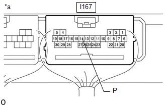
(a) Disconnect the I167 certification ECU (smart key ECU assembly) connector.
(b) Disconnect the I17 shift lock control unit assembly connector.
(c) Measure the resistance according to the value(s) in the table below.
Standard Resistance:
|
Tester Connection | Condition |
Specified Condition |
|---|---|---|
|
I167-14 (P) - I17-3 (P2) |
Always | Below 1 Ω |
|
I167-14 (P) or I17-3 (P2) - Other terminals and body ground |
Always | 10 kΩ or higher |
| OK | | REPLACE SHIFT LOCK CONTROL UNIT ASSEMBLY |
| NG | | REPAIR OR REPLACE HARNESS OR CONNECTOR |
| 10. |
CHECK HARNESS AND CONNECTOR (STOP LIGHT SWITCH ASSEMBLY - POWER SOURCE AND BODY GROUND) |
| (a) Measure the voltage according to the value(s) in the table below. Standard Voltage:
|
|
(b) Measure the resistance according to the value(s) in the table below.
Standard Resistance:
|
Tester Connection | Condition |
Specified Condition |
|---|---|---|
|
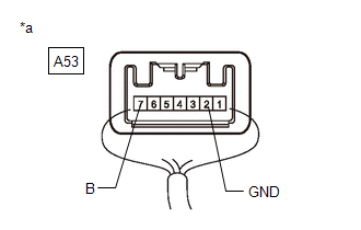
A53-2 (GND) - Body ground |
Always | Below 1 Ω |
| NG | | REPAIR OR REPLACE HARNESS OR CONNECTOR |
|
| 11. |
CHECK HARNESS AND CONNECTOR (CERTIFICATION ECU (SMART KEY ECU ASSEMBLY) - STOP LIGHT SWITCH ASSEMBLY) |
(a) Disconnect the A53 stop light switch assembly connector.
(b) Disconnect the O175 certification ECU (smart key ECU assembly) connector.
(c) Disconnect the A161 hybrid vehicle control ECU connector.
(d) Disconnect the A51 skid control ECU (brake actuator assembly) connector.
(e) Disconnect the A157 electric brake booster (brake booster with master cylinder assembly) connector.
(f) Disconnect the I17 shift lock control unit assembly connector.
(g) Measure the resistance according to the value(s) in the table below.
Standard Resistance:
|
Tester Connection | Condition |
Specified Condition |
|---|---|---|
|
O175-21 (STP1) - A53-3 (L) |
Always | Below 1 Ω |
|
O175-21 (STP1) or A53-3 (L) - Other terminals and body ground |
Always | 10 kΩ or higher |
| NG | | REPAIR OR REPLACE HARNESS OR CONNECTOR |
|
| 12. |
CHECK STOP LIGHT SWITCH ASSEMBLY |
Click here
| OK | |
REPLACE CERTIFICATION ECU (SMART KEY ECU ASSEMBLY) |
| NG | | REPLACE STOP LIGHT SWITCH ASSEMBLY |


