Toyota Corolla Cross: PBD Touch Sensor RH Circuit Circuit Open (B222B13)
DESCRIPTION
This DTC is output when the multiplex network door ECU detects a power back door sensor assembly RH touch sensor malfunction.
|
DTC No. | Detection Item |
DTC Detection Condition | Trouble Area |
|---|---|---|---|
|
B222B13 | PBD Touch Sensor RH Circuit Circuit Open |
Multiplex network door ECU detects power back door sensor assembly RH touch sensor malfunction |
|
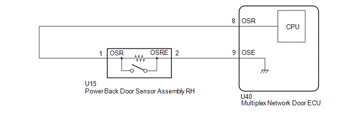
WIRING DIAGRAM
CAUTION / NOTICE / HINT
NOTICE:
If the replacement, removal and installation of the multiplex network door ECU or disconnection of the connectors of the multiplex network door ECU has been performed, initialize the power back door system.
Click here .gif)
PROCEDURE
| 1. |
CLEAR DTC |
(a) Clear the DTCs.
Body Electrical > Back Door > Clear DTCs
|
.gif)
| 2. |
CHECK FOR DTC |
(a) Check for DTCs.
Body Electrical > Back Door > Trouble Codes|
Result | Proceed to |
|---|---|
|
B222B13 is output | A |
|
B222B13 is not output |
B |
| B |
.gif) | USE SIMULATION METHOD TO CHECK |
|
| 3. |
READ VALUE USING GTS |
(a) Read the Data List according to the display on the GTS.
Body Electrical > Back Door > Data List|
Tester Display | Measurement Item |
Range | Normal Condition |
Diagnostic Note |
|---|---|---|---|---|
|
PBD Touch Sensor RH | Power back door sensor assembly RH signal |
ON, OFF or Open | Open: Power back door sensor assembly RH circuit open |
- |
|
Tester Display |
|---|
| PBD Touch Sensor RH |
|
Result | Proceed to |
|---|---|
|
The value of PBD Touch Sensor RH is Open |
A |
| None of the above conditions are met |
B |
| B |
| GO TO STEP 6 |
|
| 4. |
INSPECT POWER BACK DOOR SENSOR ASSEMBLY RH |
Click here
| NG | | REPLACE POWER BACK DOOR SENSOR ASSEMBLY RH |
|
| 5. |
CHECK HARNESS AND CONNECTOR (MULTIPLEX NETWORK DOOR ECU - POWER BACK DOOR SENSOR ASSEMBLY RH) |
(a) Disconnect the U40 multiplex network door ECU connector.
(b) Disconnect the U15 power back door sensor assembly RH connector.
(c) Measure the resistance according to the value(s) in the table below.
Standard Resistance:
|
Tester Connection | Condition |
Specified Condition |
|---|---|---|
|
U40-8 (OSR) - U15-1 (OSR) |
Always | Below 1 Ω |
|
U40-9 (OSE) - U15-2 (OSRE) |
Always | Below 1 Ω |
|
U40-8 (OSR) or U15-1 (OSR) - Body ground |
Always | 10 kΩ or higher |
|
U40-9 (OSE) or U15-2 (OSRE) - Body ground |
Always | 10 kΩ or higher |
| OK | | REPLACE MULTIPLEX NETWORK DOOR ECU |
| NG | | REPAIR OR REPLACE HARNESS OR CONNECTOR |
| 6. |
READ VALUE USING GTS |
(a) Read the Data List according to the display on the GTS.
Body Electrical > Back Door > Data List|
Tester Display | Measurement Item |
Range | Normal Condition |
Diagnostic Note |
|---|---|---|---|---|
|
PBD Touch Sensor RH | Power back door sensor assembly RH signal |
ON, OFF or Open | OFF: Power back door sensor assembly RH not pressed |
- |
|
Tester Display |
|---|
| PBD Touch Sensor RH |
|
Result | Proceed to |
|---|---|
|
The value of PBD Touch Sensor RH is OFF |
A |
| None of the above conditions are met |
B |
| B |
| GO TO STEP 4 |
|
| 7. |
READ VALUE USING GTS |
(a) Read the Data List according to the display on the GTS.
Body Electrical > Back Door > Data List|
Tester Display | Measurement Item |
Range | Normal Condition |
Diagnostic Note |
|---|---|---|---|---|
|
PBD Touch Sensor RH | Power back door sensor assembly RH signal |
ON, OFF or Open | ON: Power back door sensor assembly RH pressed |
- |
|
Tester Display |
|---|
| PBD Touch Sensor RH |
|
Result | Proceed to |
|---|---|
|
The value of PBD Touch Sensor RH is ON |
A |
| None of the above conditions are met |
B |
| A |
| REPLACE MULTIPLEX NETWORK DOOR ECU |
| B |
| GO TO STEP 4 |


