Toyota Corolla Cross: Parts Location
PARTS LOCATION
ILLUSTRATION
|
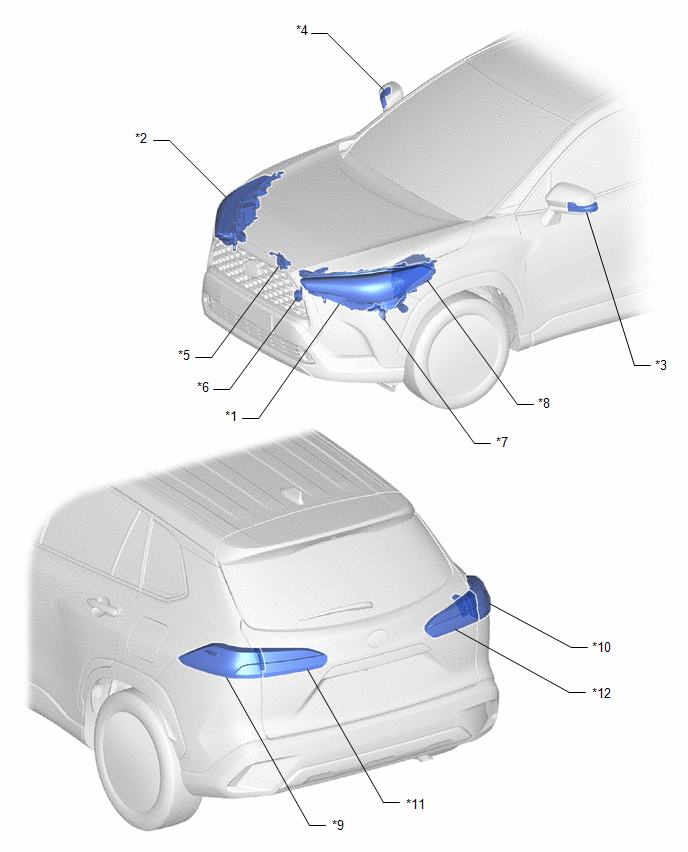
*1 | HEADLIGHT ASSEMBLY LH - TURN SIGNAL LIGHT - LOW BEAM |
*2 | HEADLIGHT ASSEMBLY RH - TURN SIGNAL LIGHT - LOW BEAM |
|
*3 | SIDE TURN SIGNAL LIGHT ASSEMBLY LH |
*4 | SIDE TURN SIGNAL LIGHT ASSEMBLY RH |
|
*5 | HOOD LOCK ASSEMBLY - ENGINE HOOD COURTESY SWITCH |
*6 | LOW PITCHED HORN ASSEMBLY |
|
*7 | SECURITY HORN ASSEMBLY |
*8 | NO. 1 ENGINE ROOM RELAY BLOCK - HORN RELAY - S-HORN RELAY - HORN FUSE - S-HORN FUSE |
|
*9 | REAR COMBINATION LIGHT ASSEMBLY LH - TURN SIGNAL LIGHT - TEILLIGHT |
*10 | REAR COMBINATION LIGHT ASSEMBLY RH - TURN SIGNAL LIGHT - TEILLIGHT |
|
*11 | REAR LIGHT ASSEMBLY LH - TEILLIGHT | *12 |
REAR LIGHT ASSEMBLY RH - TEILLIGHT |
ILLUSTRATION
|
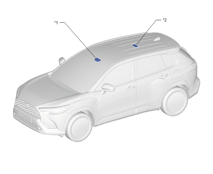
*1 | MAP LIGHT ASSEMBLY |
*2 | NO. 1 ROOM LIGHT ASSEMBLY |
ILLUSTRATION
|
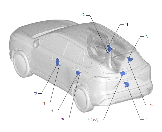
*A | w/ Power Back Door System |
- | - |
|
*1 | FRONT DOOR COURTESY LIGHT SWITCH ASSEMBLY (LH) |
*2 | FRONT DOOR COURTESY LIGHT SWITCH ASSEMBLY (RH) |
|
*3 | FRONT DOOR LOCK WITH MOTOR ASSEMBLY LH |
*4 | FRONT DOOR LOCK WITH MOTOR ASSEMBLY RH |
|
*5 | REAR DOOR COURTESY LIGHT SWITCH ASSEMBLY (LH) |
*6 | REAR DOOR COURTESY LIGHT SWITCH ASSEMBLY (RH) |
|
*7 | REAR DOOR LOCK WITH MOTOR ASSEMBLY LH |
*8 | REAR DOOR LOCK WITH MOTOR ASSEMBLY RH |
|
*9 | BACK DOOR LOCK WITH COURTESY LIGHT SWITCH ASSEMBLY |
*10 | MULTIPLEX NETWORK DOOR ECU |
ILLUSTRATION
|
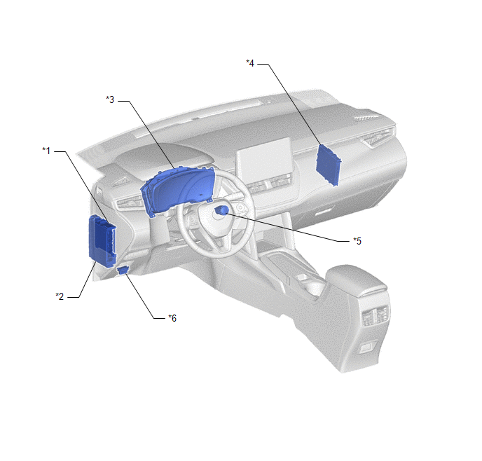
*1 | MAIN BODY ECU (MULTIPLEX NETWORK BODY ECU) |
*2 | POWER DISTRIBUTION BOX ASSEMBLY |
|
*3 | COMBINATION METER ASSEMBLY |
*4 | CERTIFICATION ECU (SMART KEY ECU ASSEMBLY) |
|
*5 | ENGINE SWITCH |
*6 | DLC3 |


