Toyota Corolla Cross: Door LIN Bus off (B232588)
DESCRIPTION
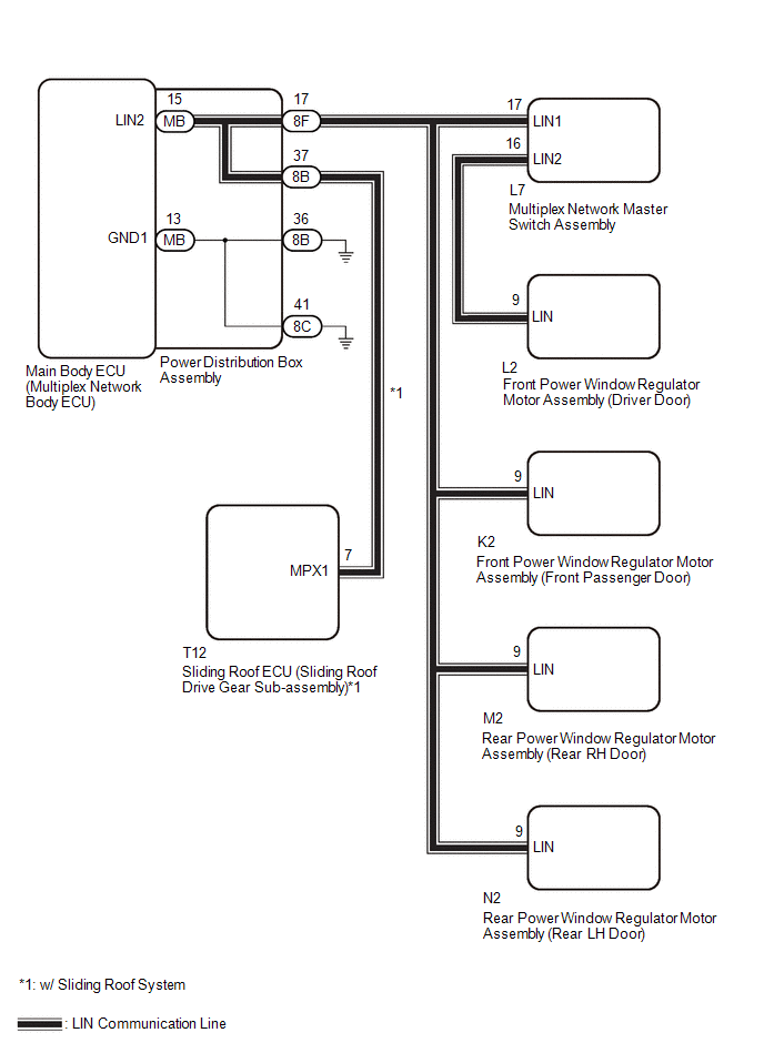
If the main body ECU (multiplex network body ECU) detects a communication error with an ECU connected to the door bus lines for 8 seconds or more, DTC B232588 will be stored.
|
DTC No. |
Detection Item |
DTC Detection Condition |
Trouble Area |
|---|---|---|---|
|
B232588 |
Door LIN Bus off |
The main body ECU (multiplex network body ECU) detects a communication error with an ECU connected to the door bus lines for 8 seconds or more. |
|
- *1: w/ Sliding Roof System
WIRING DIAGRAM
CAUTION / NOTICE / HINT
NOTICE:
- When a power window regulator motor assembly is replaced or removed and
reinstalled, it is necessary to perform initialization.
Click here
.gif)
- When the sliding roof ECU (sliding roof drive gear sub-assembly) is replaced
or removed and reinstalled, it is necessary to perform initialization.*1
Click here
- *1: w/ Sliding Roof System
- Before replacing the main body ECU (multiplex network body ECU), refer to
Registration.
- for HEV Model: Click here
- for Gasoline Model: Click here
- for HEV Model: Click here
PROCEDURE
|
1. |
CLEAR DTC |
(a) Disconnect the L2 front power window regulator motor assembly (driver door) connector.
(b) Clear the DTCs.
Body Electrical > Main Body > Clear DTCs
|
.gif)
|
2. |
CHECK FRONT POWER WINDOW REGULATOR MOTOR ASSEMBLY (DRIVER DOOR) |
(a) Wait for at least 10 seconds.
(b) Check for DTCs.
Body Electrical > Main Body > Trouble Codes|
Result |
Proceed to |
|---|---|
|
B232588 is output |
A |
|
B232588 is not output |
B |
| B | .gif) |
REPLACE FRONT POWER WINDOW REGULATOR MOTOR ASSEMBLY (DRIVER DOOR) |
|
|
3. |
CLEAR DTC |
(a) Disconnect the L7 multiplex network master switch assembly connector.
(b) Clear the DTCs.
Body Electrical > Main Body > Clear DTCs
|
|
4. |
CHECK MULTIPLEX NETWORK MASTER SWITCH ASSEMBLY |
(a) Wait for at least 10 seconds.
(b) Check for DTCs.
Body Electrical > Main Body > Trouble Codes|
Result |
Proceed to |
|---|---|
|
B232588 is output |
A |
|
B232588 is not output |
B |
| B | |
GO TO STEP 17 |
|
|
5. |
CLEAR DTC |
(a) Disconnect the K2 front power window regulator motor assembly (front passenger door) connector.
(b) Clear the DTCs.
Body Electrical > Main Body > Clear DTCs
|
|
6. |
CHECK FRONT POWER WINDOW REGULATOR MOTOR ASSEMBLY (FRONT PASSENGER DOOR) |
(a) Wait for at least 10 seconds.
(b) Check for DTCs.
Body Electrical > Main Body > Trouble Codes|
Result |
Proceed to |
|---|---|
|
B232588 is output |
A |
|
B232588 is not output |
B |
| B | |
REPLACE FRONT POWER WINDOW REGULATOR MOTOR ASSEMBLY (FRONT PASSENGER DOOR) |
|
|
7. |
CLEAR DTC |
(a) Disconnect the M2 rear power window regulator motor assembly (rear RH door) connector.
(b) Clear the DTCs.
Body Electrical > Main Body > Clear DTCs
|
|
8. |
CHECK REAR POWER WINDOW REGULATOR MOTOR ASSEMBLY (REAR RH DOOR) |
(a) Wait for at least 10 seconds.
(b) Check for DTCs.
Body Electrical > Main Body > Trouble Codes|
Result |
Proceed to |
|---|---|
|
B232588 is output |
A |
|
B232588 is not output |
B |
| B | |
REPLACE REAR POWER WINDOW REGULATOR MOTOR ASSEMBLY (REAR RH DOOR) |
|
|
9. |
CLEAR DTC |
(a) Disconnect the N2 rear power window regulator motor assembly (rear LH door) connector.
(b) Clear the DTCs.
Body Electrical > Main Body > Clear DTCs
|
|
10. |
CHECK REAR POWER WINDOW REGULATOR MOTOR ASSEMBLY (REAR LH DOOR) |
(a) Wait for at least 10 seconds.
(b) Check for DTCs.
Body Electrical > Main Body > Trouble Codes|
Result |
Proceed to |
|---|---|
|
B232588 is output |
A |
|
B232588 is not output |
B |
| B | |
REPLACE REAR POWER WINDOW REGULATOR MOTOR ASSEMBLY (REAR LH DOOR) |
|
|
11. |
CHECK VEHICLE TYPE |
(a) Check the vehicle specification.
|
Result |
Proceed to |
|---|---|
|
w/ Sliding Roof System |
A |
|
w/o Sliding Roof System |
B |
| B | |
GO TO STEP 14 |
|
|
12. |
CLEAR DTC |
(a) Disconnect the T12 sliding roof ECU (sliding roof drive gear sub-assembly) connector.
(b) Clear the DTCs.
Body Electrical > Main Body > Clear DTCs
|
|
13. |
CHECK SLIDING ROOF ECU (SLIDING ROOF DRIVE GEAR SUB-ASSEMBLY) |
(a) Wait for at least 10 seconds.
(b) Check for DTCs.
Body Electrical > Main Body > Trouble Codes|
Result |
Proceed to |
|---|---|
|
B232588 is output |
A |
|
B232588 is not output |
B |
| A | |
GO TO STEP 14 |
| B | |
REPLACE SLIDING ROOF ECU (SLIDING ROOF DRIVE GEAR SUB-ASSEMBLY) |
|
14. |
CHECK HARNESS AND CONNECTOR (POWER DISTRIBUTION BOX ASSEMBLY - EACH ECU) |
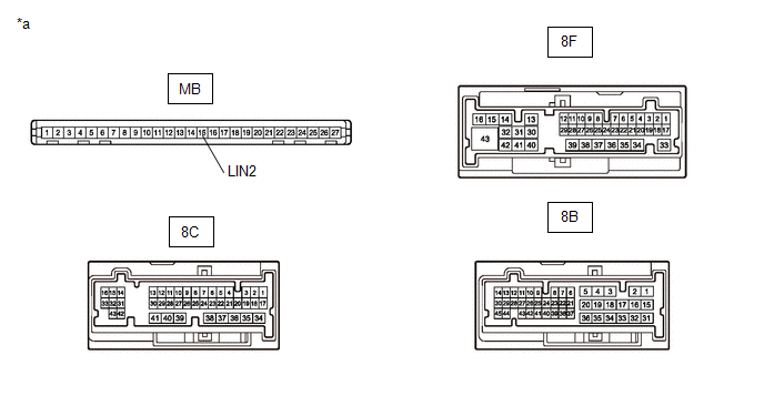
(a) Disconnect the 8B and 8F power distribution box assembly connectors.
(b) Measure the resistance according to the value(s) in the table below.
Standard Resistance:
|
Tester Connection |
Condition |
Specified Condition |
|---|---|---|
|
8F-17 - Body ground |
Always |
10 kΩ or higher |
|
8F-17 - Other terminals |
Always |
10 kΩ or higher |
|
8B-37 - Body ground |
Always |
10 kΩ or higher |
|
8B-37 - Other terminals |
Always |
10 kΩ or higher |
| NG | |
REPAIR OR REPLACE HARNESS OR CONNECTOR |
|
|
15. |
INSPECT POWER DISTRIBUTION BOX ASSEMBLY |
(a) Remove the power distribution box assembly.
HINT:
Click here
(b) Remove the main body ECU (multiplex network body ECU) from the power distribution box assembly.
|
*a |
Component without harness connected (Power Distribution Box Assembly) |
- |
- |
(c) Measure the resistance according to the value(s) in the table below.
HINT:
This inspection is to check the LIN communication line in the power distribution box assembly that connects the wire harness to the built-in main body ECU (multiplex network body ECU).
Standard Resistance:
|
Tester Connection |
Condition |
Specified Condition |
|---|---|---|
|
8B-37 - 8B-36 |
Always |
10 kΩ or higher |
|
8B-37 - 8C-41 |
Always |
10 kΩ or higher |
|
8F-17 - 8B-36 |
Always |
10 kΩ or higher |
|
8F-17 - 8C-41 |
Always |
10 kΩ or higher |
|
MB-15 (LIN2) - Other terminals |
Always |
10 kΩ or higher |
| NG | |
REPLACE POWER DISTRIBUTION BOX ASSEMBLY |
|
|
16. |
CHECK MAIN BODY ECU (MULTIPLEX NETWORK BODY ECU) |
(a) Install the main body ECU (multiplex network body ECU) to the power distribution box assembly.
(b) Connect all power distribution box assembly connectors.
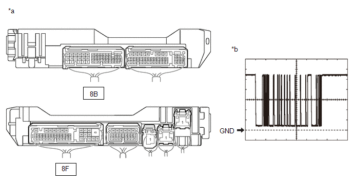
(c) Using the GTS, check the waveform.
|
*a |
Component with harness connected (Power Distribution Box Assembly) |
*b |
Waveform |
HINT:
This inspection is to check the LIN communication line in the power distribution box assembly that connects the wire harness to the built-in main body ECU (multiplex network body ECU).
OK:
|
Tester Connection |
Switch Condition |
Tool Setting |
Specified Condition |
|---|---|---|---|
|
8B-37 - Body ground |
Ignition switch ON |
2 V/DIV., 200 ms/DIV. |
Pulse generation (See waveform) |
|
8F-17 - Body ground |
Ignition switch ON |
2 V/DIV., 200 ms/DIV. |
Pulse generation (See waveform) |
| OK | |
USE SIMULATION METHOD TO CHECK |
| NG | |
REPLACE MAIN BODY ECU (MULTIPLEX NETWORK BODY ECU) |
|
17. |
CHECK HARNESS AND CONNECTOR (MULTIPLEX NETWORK MASTER SWITCH ASSEMBLY - FRONT POWER WINDOW REGULATOR MOTOR ASSEMBLY (DRIVER DOOR)) |
(a) Measure the resistance according to the value(s) in the table below.
Standard Resistance:
|
Tester Connection |
Condition |
Specified Condition |
|---|---|---|
|
L7-16 (LIN2) - Body ground |
Always |
Below 1 Ω |
|
L7-16 (LIN2) - Other terminals |
Always |
Below 1 Ω |
| OK | |
REPLACE MULTIPLEX NETWORK MASTER SWITCH ASSEMBLY |
| NG | |
REPAIR OR REPLACE HARNESS OR CONNECTOR |


