Toyota Corolla Cross: On-vehicle Inspection
ON-VEHICLE INSPECTION
CAUTION / NOTICE / HINT
HINT:
- Use the same procedure for the RH side and LH side.
- The following procedure is for the LH side.
PROCEDURE
1. REMOVE REAR WHEEL
Click here .gif)
2. DISCONNECT NO. 2 PARKING BRAKE WIRE ASSEMBLY
Click here
3. SEPARATE REAR FLEXIBLE HOSE
Click here
4. SEPARATE REAR DISC BRAKE CALIPER ASSEMBLY
Click here
5. REMOVE REAR DISC
Click here
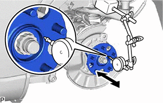
6. INSPECT REAR AXLE HUB BEARING LOOSENESS
|
(a) Using a dial indicator with magnetic base, check for looseness near
the center of the rear axle hub.
Maximum Looseness:
0.05 mm (0.00197 in.)
NOTICE:
- Ensure that the dial indicator is set perpendicular to the measurement
surface.
- Keep the magnet of the dial indicator away from the rear skid control
sensor.
(1) If the looseness exceeds the maximum, replace the rear axle hub and
bearing assembly.
|
|
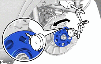
7. INSPECT REAR AXLE HUB RUNOUT
|
(a) Using a dial indicator with magnetic base, check for runout on the
surface of the rear axle hub outside the rear axle hub bolts.
Maximum Runout:
0.07 mm (0.00276 in.)
NOTICE:
- Ensure that the dial indicator is set perpendicular to the measurement
surface.
- Make sure to install the tip of the dial indicator towards the outside
of the rear axle hub bolts.
- Keep the magnet of the dial indicator away from the rear skid control
sensor.
|
|
(b) If the runout exceeds the maximum, replace the rear axle hub and bearing
assembly.
8. INSTALL REAR DISC
Click here
9. INSTALL REAR DISC BRAKE CALIPER ASSEMBLY
Click here
10. INSTALL REAR FLEXIBLE HOSE
Click here
11. CONNECT NO. 2 PARKING BRAKE WIRE ASSEMBLY
Click here
12. INSTALL REAR WHEEL
Click here
READ NEXT:
REMOVAL
CAUTION / NOTICE / HINT
COMPONENTS (REMOVAL)
Procedure
Part Name Code
1
REAR WHEEL
-
-
INSTALLATION
CAUTION / NOTICE / HINT
COMPONENTS (INSTALLATION)
Procedure
Part Name Code
1
REAR AXLE HUB AND BEARING ASS
Components
COMPONENTS
ILLUSTRATION
*1
REAR AXLE HUB BOLT
*2
REAR DISC BRAKE CALIPER ASSEMBLY
*3
REAR DISC
*4
SEE MORE:
DESCRIPTION
The ABS solenoid relay and solenoid valves are built into the
brake actuator assembly.
The rear solenoid valve RH controls the brake fluid pressure
of the rear wheel cylinder RH of the vehicle.
When this DTC is stored, the fail-safe function operates and
the ABS solenoid relay i
DESCRIPTION The throttle position sensor is built into the throttle body with motor assembly and detects the opening angle of the throttle valve. This sensor is a non-contact type sensor. It uses Hall-effect elements in order to yield accurate signals even in extreme driving conditions, such as at h