Toyota Corolla Cross: Microphone Circuit Open (B157213)
DESCRIPTION
This DTC is stored when the DCM (telematics transceiver) detects a malfunction in the telephone microphone assembly circuit.
|
DTC No. |
Detection Item |
DTC Detection Condition |
Trouble Area |
|---|---|---|---|
|
B157213 |
Microphone Circuit Open |
Current at terminal MCVD is lower than the malfunction threshold for 10 seconds or more while the ignition switch is ON |
|
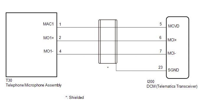
WIRING DIAGRAM
CAUTION / NOTICE / HINT
NOTICE:
Depending on the parts that are replaced during vehicle inspection or maintenance, performing initialization, registration or calibration may be needed. Refer to Precaution for Safety Connect System.
Click here .gif)
PROCEDURE
|
1. |
CHECK DTC |
(a) Turn the ignition switch to ON and wait for 10 seconds or more.
(b) Clear the DTCs.
Body Electrical > Telematics > Clear DTCs(c) Check for DTCs and check that no DTCs are output.
Body Electrical > Telematics > Trouble CodesOK:
No DTCs are output.
| OK | .gif)
|
USE SIMULATION METHOD TO CHECK |
|
.gif)
|
2. |
CHECK HARNESS AND CONNECTOR (DCM [TELEMATICS TRANSCEIVER] - TELEPHONE MICROPHONE ASSEMBLY) |
(a) Disconnect the I200 DCM (telematics transceiver) connector.
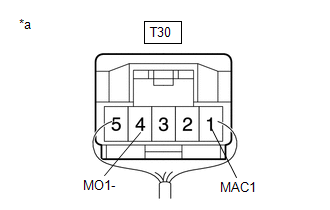
(b) Disconnect the T30 telephone Microphone Assembly connector.
(c) Measure the resistance according to the value(s) in the table below.
Standard Resistance:
|
Tester Connection |
Condition |
Specified Condition |
|---|---|---|
|
I200-5 (MCVD) - T30-1 (MAC1) |
Always |
Below 1 Ω |
|
I200-6 (MCI+) - T30-2 (MO1+) |
Always |
Below 1 Ω |
|
I200-7 (MCI-) - T30-4 (MO1-) |
Always |
Below 1 Ω |
|
I200-23 (SGND) - Body ground |
Always |
10 kΩ or higher |
|
I200-5 (MCVD) or T30-1 (MAC1) - Body ground |
Always |
10 kΩ or higher |
|
I200-6 (MCI+) or T30-2 (MO1+) - Body ground |
Always |
10 kΩ or higher |
|
I200-7 (MCI-) or T30-4 (MO1-) - Body ground |
Always |
10 kΩ or higher |
| NG |
|
REPAIR OR REPLACE HARNESS OR CONNECTOR |
|
|
3. |
CHECK DCM (TELEMATICS TRANSCEIVER) (TELEPHONE MICROPHONE ASSEMBLY POWER SOURCE) |
|
(a) Remove the telephone microphone assembly but do not disconnect the connectors. Click here |
|
(b) Measure the voltage and resistance according to the value(s) in the table below.
Standard Voltage:
|
Tester Connection |
Switch Condition |
Specified Condition |
|---|---|---|
|
T30-1 (MAC1) - Body ground |
Ignition switch ON |
4 to 6 V |
Standard Resistance:
|
Tester Connection |
Condition |
Specified Condition |
|---|---|---|
|
T30-4 (MO1-) - Body ground |
Always |
Below 1 Ω |
| OK |
|
REPLACE TELEPHONE MICROPHONE ASSEMBLY |
|
|
4. |
REPLACE DCM (TELEMATICS TRANSCEIVER) |
(a) Replace the DCM (telematics transceiver) with a new one.
Click here
NOTICE:
- The ignition switch must be off.
- Do not exchange the DCM (telematics transceiver) with one from another vehicle.
| NEXT |
|
PERFORM DCM ACTIVATION |


