Toyota Corolla Cross: Airbag Signal Signal Plausibility Failure (B15C464)
DESCRIPTION
If the DCM (telematics transceiver) detects an error in communication between the DCM (telematics transceiver) and the airbag ECU assembly as a result of the DCM (telematics transceiver) self check, this DTC will be stored.
|
DTC No. |
Detection Item |
DTC Detection Condition |
Trouble Area |
|---|---|---|---|
|
B15C464 |
Airbag Signal Signal Plausibility Failure |
DCM (telematics transceiver) detects an error in signals from airbag ECU assembly when ignition switch is ON. |
|
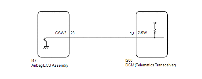
WIRING DIAGRAM
CAUTION / NOTICE / HINT
NOTICE:
- The vehicle is equipped with an SRS (Supplemental Restraint System)
which includes components such as airbags. Before servicing (including removal
or installation of parts), be sure to read the Precaution in the SRS.
Click here
.gif)
- After turning the ignition switch off, waiting time may be required
before disconnecting the cable from the negative (-) auxiliary battery terminal.
Click here
HINT:
When disconnecting and reconnecting the auxiliary battery, there is an automatic learning function that completes learning when the respective system is used.
Click here
PROCEDURE
|
1. |
CHECK DTC (AIRBAG SYSTEM) |
(a) Turn the ignition switch to ON and wait for 10 seconds or more.
(b) Clear the DTCs.
(c) Check for DTCs and check that no DTCs are output.
OK:
No DTCs are output.
| NG | .gif)
|
GO TO AIRBAG SYSTEM |
|
.gif)
|
2. |
CHECK DTC |
(a) Turn the ignition switch to ON and wait for 10 seconds or more.
(b) Clear the DTCs.
Body Electrical > Telematics > Clear DTCs(c) Check for DTCs and check that no DTCs are output.
Body Electrical > Telematics > Trouble CodesOK:
No DTCs are output.
| OK |
|
USE SIMULATION METHOD TO CHECK |
|
|
3. |
CHECK DCM (TELEMATICS TRANSCEIVER) (GSW SIGNAL) |
|
(a) Remove the DCM (telematics transceiver) but do not disconnect the connectors. Click here |
|
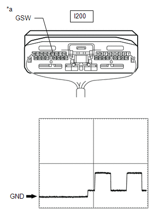
(b) Check the input waveform.
(1) Check the signal waveform according to the condition(s) in the table below. (Check the waveform from the back of the wire harness connector of the DCM (telematics transceiver) while the airbag ECU assembly connectors are connected.)
Reference Waveform:
|
Item |
Condition |
|---|---|
|
Tester connection |
I200-13 (GSW) - Body ground |
|
Tool setting |
5.0 V/DIV., 20 ms./DIV. |
|
Vehicle condition |
Ignition switch ON |
OK:
The waveform is similar to that shown in the illustration.
| NG |
|
GO TO STEP 5 |
|
|
4. |
REPLACE DCM (TELEMATICS TRANSCEIVER) |
(a) Replace the DCM (telematics transceiver) with a new one.
Click here
NOTICE:
- The ignition switch must be off.
- Do not exchange the DCM (telematics transceiver) with one from another vehicle.
| NEXT |
|
PERFORM DCM ACTIVATION |
|
5. |
CHECK HARNESS AND CONNECTOR (DCM [TELEMATICS TRANSCEIVER] - AIRBAG ECU ASSEMBLY) |
(a) Disconnect the I200 DCM (telematics transceiver) connector.
(b) Disconnect the I47 airbag ECU assembly connector.
(c) Measure the resistance according to the value(s) in the table below.
Standard Resistance:
|
Tester Connection |
Condition |
Specified Condition |
|---|---|---|
|
I200-13 (GSW) - I47-23 (GSW3) |
Always |
Below 1 Ω |
|
I200-13 (GSW) - Body ground |
Always |
10 kΩ or higher |
| OK |
|
REPLACE AIRBAG ECU ASSEMBLY |
| NG |
|
REPLACE HARNESS OR CONNECTOR |


