Toyota Corolla Cross: Load Sensor for Occupant Detection System Circuit Voltage Below Threshold (B179316)
DESCRIPTION
|
DTC No. | Detection Item |
DTC Detection Condition | Trouble Area |
Warning Indicate | Test Mode / Check Mode |
|---|---|---|---|---|---|
|
B179316 | Load Sensor for Occupant Detection System Circuit Voltage Below Threshold |
When the detected voltage is below specified value before supplying power to the sensor. |
| Comes on |
Does not apply to test/check mode |
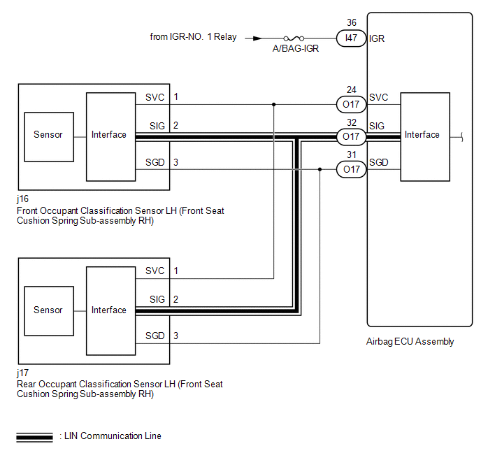
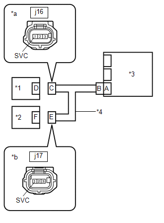
- *: The front occupant classification sensor LH and rear occupant classification sensor LH are built into the front seat cushion spring sub-assembly RH.
WIRING DIAGRAM
CAUTION / NOTICE / HINT
NOTICE:
- After the ignition switch is turned off, there may be a waiting time before disconnecting the negative (-) battery terminal.
Click here
.gif)
HINT:
When disconnecting and reconnecting the battery, there is an automatic learning function that completes learning when the respective system is used.
Click here
- Inspect the fuses for circuits related to this system before performing the following procedure.
HINT:
- If it is difficult to perform troubleshooting (wire harness inspection), remove the front passenger seat installation bolts to see under the seat cushion.
- In the above case, lift and hold the seat so that it does not fall down. Hold the seat only as necessary because holding the seat for a long period of time may cause seat rail deformation.
PROCEDURE
|
1. | CHECK CONNECTION OF CONNECTORS |
(a) Turn the ignition switch off.
(b) Disconnect the cable from the negative (-) battery terminal.
CAUTION:
Wait at least 60 seconds after disconnecting the cable from the negative (-) battery terminal to disable the SRS system.
(c) Check that the connectors are properly connected to the airbag ECU assembly, front occupant classification sensor LH and rear occupant classification sensor LH.
OK:
The connectors are properly connected.
| NG | .gif) | CONNECT CONNECTORS PROPERLY |
|
.gif)
| 2. |
CHECK CONNECTORS |
(a) Disconnect the connectors from the airbag ECU assembly, front occupant classification sensor LH and rear occupant classification sensor LH.
| (b) Check that the terminals of the connectors are not deformed or damaged. OK: The terminals of the connectors are not deformed or damaged. |
|
.png)
| NG | | REPAIR OR REPLACE HARNESS OR CONNECTOR |
|
| 3. |
CHECK HARNESS AND CONNECTOR (AIRBAG ECU ASSEMBLY - BATTERY) |
(a) Disconnect the connector from the airbag ECU assembly.
(b) Connect the cable to the negative (-) battery terminal.
(c) Turn the ignition switch to ON.
(d) Operate all components of the electrical systems (defogger, wipers, headlights, heater blower, etc.).
| (e) Measure the voltage according to the value(s) in the table below. Standard Voltage:
Result:
|
|
.png)
(f) Turn the ignition switch off.
(g) Disconnect the cable from the negative (-) battery terminal.
CAUTION:
Wait at least 60 seconds after disconnecting the cable from the negative (-) battery terminal to disable the SRS system.
| NG | | REPAIR OR REPLACE HARNESS OR CONNECTOR |
|
| 4. |
CHECK HARNESS AND CONNECTOR (AIRBAG ECU ASSEMBLY - FRONT OCCUPANT CLASSIFICATION SENSOR LH - REAR OCCUPANT CLASSIFICATION SENSOR LH) |
| (a) Measure the resistance according to the value(s) in the table below. Standard Resistance:
|
|
.png)
| NG | | REPAIR OR REPLACE HARNESS OR CONNECTOR |
|
| 5. |
CHECK AIRBAG ECU ASSEMBLY |
(a) Connect the connectors to the airbag sensor assembly.
(b) Connect the cable to the negative (-) auxiliary battery terminal.
(c) Turn the ignition switch to ON.
| (d) Measure the voltage according to the value(s) in the table below. Standard Voltage:
Result:
|
|
(e) Turn the ignition switch off.
(f) Disconnect the cable from the negative (-) auxiliary battery terminal.
CAUTION:
Wait at least 60 seconds after disconnecting the cable from the negative (-) auxiliary battery terminal to disable the SRS system.
| OK | | REPLACE FRONT SEAT CUSHION SPRING SUB-ASSEMBLY RH |
| NG | | REPLACE AIRBAG ECU ASSEMBLY |
READ NEXT:
 Load Sensor for Occupant Detection System Circuit Voltage Above Threshold (B179317)
DESCRIPTION
DTC No. Detection Item
DTC Detection Condition Trouble Area
Warning Indicate Test Mode / Check Mode
B179317 Load Sensor for Occupant Detection System Circui
Trouble in Passenger Airbag ON/OFF Indicator
DESCRIPTION The occupant classification system detects the front passenger seat condition. It then displays the instrument panel passenger without door airbag assembly and front seat cushion spring su
LIN Communication Circuit
DESCRIPTION
Error Code Detection Item
DTC Detection Condition Trouble Area
17 FI LIN Communication Lost
When a communication malfunction with the load sensor is detected
SEE MORE:
 Test Mode Procedure
TEST MODE PROCEDURE
REAR BRAKE PAD REPLACEMENT MODE
*1
Rear Disc Brake Piston
*2
Nut
*a
The nut moves inward in pad replacement mode
HINT:
When replacing the rear disc brake pad and rear disc, since the
nu
Diagnostic Trouble Code Chart
DIAGNOSTIC TROUBLE CODE CHART
Intuitive Parking Assist System
DTC No.
Detection Item
Link
C161504
Clearance Warning ECU System Internal Failure
C1AE187
Ultrasonic Sensor (Front Left Corner) Missin
