Toyota Corolla Cross: Test Mode Procedure
TEST MODE PROCEDURE
REAR BRAKE PAD REPLACEMENT MODE
|
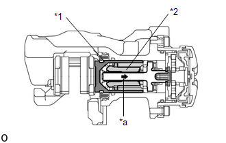
*1 |
Rear Disc Brake Piston |
|
*2 |
Nut |
|
*a |
The nut moves inward in pad replacement mode |
HINT:
When replacing the rear disc brake pad and rear disc, since the nut inside the rear disc brake cylinder assembly is in an advanced position, it is necessary to move the nut back inside the cylinder. The nut can be moved back using pad replacement mode.
(a) Pad replacement mode
When Using the GTS:- Enter the following menus: Chassis / Brake/EPB / Utility / EPB Full
Release
NOTICE:
The parking brake must be released.
- Follow the GTS display and select "Next".
- Push and hold the electric parking brake switch (electric parking brake
switch assembly) to the release side for 5 seconds or more.
NOTICE:
- Make sure to perform this procedure with the ignition switch to ON.
- Make sure that the brake pedal is not depressed when performing this procedure.
- When the system changes to pad replacement mode, DTC C060E2A, C06132A or C13B800 may be stored. If the DTC is stored, clear the DTCs after the procedure (rear brake pad replacement, etc.) is complete.
HINT:
Once the operation finishes, the parking brake indicator light flashes slowly (1 second intervals) (nut moves back inside the cylinder and system enters pad replacement mode).
|
Tester Display |
|---|
|
EPB Full Release |
- Turn the ignition switch off.
- Turn the ignition switch to ON.
- Within 8 seconds, operate the electric parking brake switch (electric
parking brake switch assembly) to perform 3 lock side ON operations (from
off (release) to on (pull)) and then 3 release side ON operations (from
off (release) to on (push)).
NOTICE:
- If the operation is performed too quickly, the system may not respond. If the system does not respond, perform the operation again at a slower speed.
- The parking brake must be released.
HINT:
The parking brake indicator light (red) flashes (0.25 second intervals).
- Push and hold the electric parking brake switch (electric parking brake
switch assembly) to the release side for 5 seconds or more.
NOTICE:
- Make sure to perform this procedure with the ignition switch to ON.
- Make sure that the brake pedal is not depressed when performing this procedure.
- When the system changes to pad replacement mode, DTC C060E2A, C06132A or C13B800 may be stored. If the DTC is stored, clear the DTCs after the procedure (rear brake pad replacement, etc.) is complete.
HINT:
After a short time passes, the parking brake actuator assembly operates, and once the assembly finishes operating, the parking brake indicator light flashes slowly (1 second intervals) (nut moves back inside the cylinder and system enters pad replacement mode).
(b) Turn the ignition switch off.
NOTICE:
Do not operate the electric parking brake switch (electric parking brake switch assembly) until the procedure is complete. If operated, the system will return to its normal condition.
When Using the GTS:- Disconnect the GTS from the DLC3.
(c) Normal condition recovery
(1) After the procedure (rear brake pad replacement, etc.) is complete, turn the ignition switch to ON and pull the electric parking brake switch (electric parking brake switch assembly) to the lock side for 5 seconds or more.
NOTICE:
- When performing work (replacing the rear brake pad, etc.), do not operate the electric parking brake switch (electric parking brake switch assembly) or turn the ignition switch to ON and operate the shift lever. If the electric parking brake switch (electric parking brake switch assembly) or shift lever is operated, the parking brake may operate and the rear disc brake piston may fall off. Also, make sure to disconnect the connector of the parking brake actuator assembly or disconnect the cable from the negative (-) auxiliary battery terminal.
- When DTC C060E2A, C06132A or C13B800 is stored, clear the DTCs.


