Toyota Corolla Cross: Left Side Restraints Sensor 5 Signal Plausibility Failure (B009B64)
DESCRIPTION
|
DTC No. | Detection Item |
DTC Detection Condition | Trouble Area |
Warning Indicate | Test Mode / Check Mode |
|---|---|---|---|---|---|
|
B009B64 | Left Side Restraints Sensor 5 Signal Plausibility Failure |
Either condition is met:
|
| Comes on |
Not applicable |
|
Vehicle Condition | |||
|---|---|---|---|
|
Pattern 1 | Pattern 2 | ||
|
Diagnosis Condition | Ignition switch ON |
○ | ○ |
|
Malfunction Status | Side airbag pressure sensor LH malfunction |
○ | - |
|
Airbag ECU assembly malfunction |
- | ○ | |
|
Detection Time | - |
- | |
|
Number of Trips | 1 trip |
1 trip | |
HINT:
DTC will be output when conditions for either of the patterns in the table above are met.
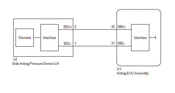
WIRING DIAGRAM
CAUTION / NOTICE / HINT
NOTICE:
- After the ignition switch is turned off, there may be a waiting time before disconnecting the negative (-) battery terminal.
Click here
.gif)
HINT:
When disconnecting and reconnecting the battery, there is an automatic learning function that completes learning when the respective system is used.
Click here
- After replacing the airbag ECU assembly, refer to initialization.
Click here
PROCEDURE
|
1. | CHECK SIDE AIRBAG PRESSURE SENSOR LH |
| (a) Turn the ignition switch off. |
|
(b) Disconnect the cable from the negative (-) battery terminal.
CAUTION:
Wait at least 60 seconds after disconnecting the cable from the negative (-) battery terminal to disable the SRS system.
(c) Interchange the side airbag pressure sensor LH with RH and connect the connectors.
(d) Connect the cable to the negative (-) battery terminal.
(e) Turn the ignition switch to ON, and wait for at least 60 seconds.
(f) Clear the DTCs stored in memory.
Body Electrical > SRS Airbag > Clear DTCs
|
.gif)
| 2. |
CHECK SIDE AIRBAG PRESSURE SENSOR LH |
(a) Turn the ignition switch off.
(b) Turn the ignition switch to ON, and wait for at least 60 seconds.
(c) Check for DTCs.
Body Electrical > SRS Airbag > Trouble Codes| Result |
Proceed to |
|---|---|
| B009B64 is output |
A |
| B009E64 is output |
B |
| B009B64 and B009E64 are not output |
C |
HINT:
Codes other than DTCs B009B64 and B009E64 may be output at this time, but they are not related to this check.
(d) Turn the ignition switch off.
(e) Disconnect the cable from the negative (-) battery terminal.
CAUTION:
Wait at least 60 seconds after disconnecting the cable from the negative (-) battery terminal to disable the SRS system.
(f) Return the side airbag pressure sensor LH and RH to their original positions and connect the connectors.
| A |
.gif) | REPLACE AIRBAG ECU ASSEMBLY |
| B |
| REPLACE SIDE AIRBAG PRESSURE SENSOR LH |
| C |
| USE SIMULATION METHOD TO CHECK |


