Toyota Corolla Cross: Left Side Restraints Sensor 2 Value of Signal Protection Calculation Incorrect (B009283)
DESCRIPTION
|
DTC No. | Detection Item |
DTC Detection Condition | Trouble Area |
Warning Indicate | Test Mode / Check Mode |
|---|---|---|---|---|---|
|
B009283 | Left Side Restraints Sensor 2 Value of Signal Protection Calculation Incorrect |
One of the following conditions is met:
|
| Comes on |
Does not apply to test/check mode |
|
Vehicle Condition | |||||||
|---|---|---|---|---|---|---|---|
|
Pattern 1 | Pattern 2 |
Pattern 3 | Pattern 4 |
Pattern 5 | Pattern 6 | ||
|
Diagnosis Condition | Ignition switch ON |
○ | ○ |
○ | ○ |
○ | ○ |
|
Malfunction Status | The airbag ECU assembly detects a line short circuit signal in the side collision sensor LH circuit (bus 2). |
○ | - |
- | - |
- | - |
|
The airbag ECU assembly detects an open circuit signal in the side collision sensor LH circuit (bus 2). |
- | ○ |
- | - |
- | - | |
|
The airbag ECU assembly detects a short circuit to ground signal in the side collision sensor LH circuit (bus 2). |
- | - |
○ | - |
- | - | |
|
The airbag ECU assembly detects a short circuit to B+ signal in the side collision sensor LH circuit (bus 2). |
- | - |
- | ○ |
- | - | |
|
No. 1 side airbag sensor LH malfunction |
- | - |
- | - |
○ | - | |
|
Airbag ECU assembly malfunction |
- | - |
- | - |
- | ○ | |
|
Detection Time | 2 seconds |
2 seconds | 2 seconds |
2 seconds | 2 seconds |
2 seconds | |
|
Number of Trips | 1 trip |
1 trip | 1 trip |
1 trip | 1 trip |
1 trip | |
HINT:
DTC will be output when conditions for either of the patterns in the table above are met.
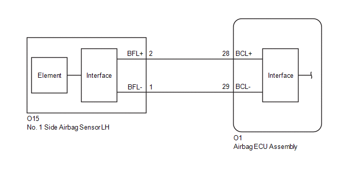
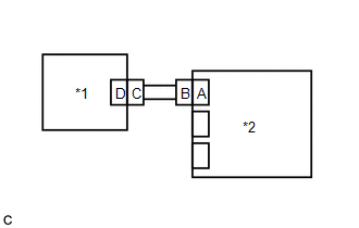
WIRING DIAGRAM
CAUTION / NOTICE / HINT
NOTICE:
After the ignition switch is turned off, there may be a waiting time before disconnecting the negative (-) battery terminal.
Click here .gif)
HINT:
When disconnecting and reconnecting the battery, there is an automatic learning function that completes learning when the respective system is used.
Click here
PROCEDURE
| 1. |
CHECK CONNECTION OF CONNECTORS |
(a) Turn the ignition switch off.
(b) Disconnect the cable from the negative (-) battery terminal.
CAUTION:
Wait at least 60 seconds after disconnecting the cable from the negative (-) battery terminal to disable the SRS system.
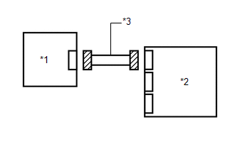
(c) Check that the connectors are properly connected to the airbag ECU assembly and No. 1 side airbag sensor LH.
OK:
The connectors are properly connected.
| NG | .gif) | CONNECT CONNECTORS PROPERLY |
|
.gif)
| 2. |
CHECK CONNECTORS |
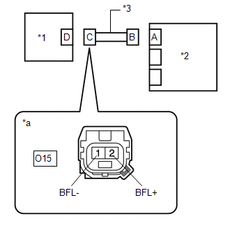
(a) Disconnect the connectors from the airbag ECU assembly and No. 1 side airbag sensor LH.
| (b) Check that the terminals of the connectors are not deformed or damaged. OK: The terminals of the connectors are not deformed or damaged. |
|
| NG | | REPAIR OR REPLACE HARNESS OR CONNECTOR |
|
| 3. |
CHECK HARNESS AND CONNECTOR (SHORT) |
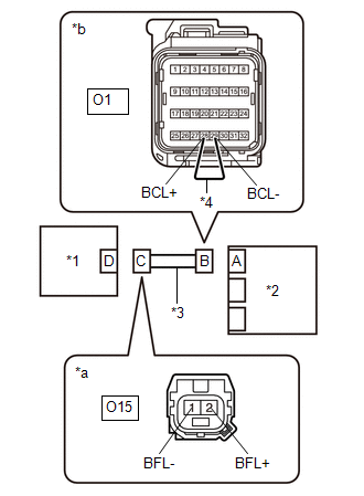
| (a) Measure the resistance according to the value(s) in the table below. Standard Resistance:
|
|
| NG | | REPAIR OR REPLACE HARNESS OR CONNECTOR |
|
| 4. |
CHECK HARNESS AND CONNECTOR (SHORT TO GROUND) |
| (a) Measure the resistance according to the value(s) in the table below. Standard Resistance:
|
|
| NG | | REPAIR OR REPLACE HARNESS OR CONNECTOR |
|
| 5. |
CHECK HARNESS AND CONNECTOR (SHORT TO B+) |
(a) Connect the cable to the negative (-) battery terminal.
(b) Turn the ignition switch to ON.
| (c) Measure the voltage according to the value(s) in the table below. Standard Voltage:
Result:
|
|
(d) Turn the ignition switch off.
(e) Disconnect the cable from the negative (-) battery terminal.
CAUTION:
Wait at least 60 seconds after disconnecting the cable from the negative (-) battery terminal to disable the SRS system.
| NG | | REPAIR OR REPLACE HARNESS OR CONNECTOR |
|
| 6. |
CHECK HARNESS AND CONNECTOR (OPEN) |
(a) Using a service wire, connect terminals 28 (BCL+) and 29 (BCL-) of connector B.
NOTICE:
Do not forcibly insert the service wire into the terminals of the connector when connecting the wire.
| (b) Measure the resistance according to the value(s) in the table below. Standard Resistance:
Result:
|
|
(c) Disconnect the service wire from connector B.
| NG | | REPAIR OR REPLACE HARNESS OR CONNECTOR |
|
| 7. |
CLEAR DTC |
| (a) Connect the connector to the airbag ECU assembly. |
|
(b) Interchange the No. 1 side airbag sensor LH with RH and connect the connectors.
(c) Connect the cable to the negative (-) battery terminal.
(d) Turn the ignition switch to ON, and wait for at least 60 seconds.
(e) Clear the DTCs stored in memory.
Body Electrical > SRS Airbag > Clear DTCs(f) Turn the ignition switch off.
|
| 8. |
CHECK NO. 1 SIDE AIRBAG SENSOR LH |
(a) Turn the ignition switch to ON, and wait for at least 60 seconds.
(b) Check for DTCs.
Body Electrical > SRS Airbag > Trouble Codes| Result |
Proceed to |
|---|---|
| B009283 is output |
A |
| B009783 is output |
B |
| B009283 and B009783 are not output |
C |
HINT:
Codes other than DTCs B009283 and B009783 may be output at this time, but they are not related to this check.
(c) Turn the ignition switch off.
(d) Disconnect the cable from the negative (-) battery terminal.
CAUTION:
Wait at least 60 seconds after disconnecting the cable from the negative (-) battery terminal to disable the SRS system.
(e) Return the No. 1 side airbag sensor LH and RH to their original positions and connect the connectors.
| A |
| REPLACE AIRBAG ECU ASSEMBLY |
| B |
| REPLACE NO. 1 SIDE AIRBAG SENSOR LH |
| C |
| USE SIMULATION METHOD TO CHECK |
READ NEXT:
 Left Side Restraints Sensor 2 Signal Below Allowable Range (B009284)
DESCRIPTION
DTC No. Detection Item
DTC Detection Condition Trouble Area
Warning Indicate Test Mode / Check Mode
B009284 Left Side Restraints Sensor 2 Signal Below Allow
Left Side Restraints Sensor 2 Signal Above Allowable Range (B009285)
DESCRIPTION
DTC No. Detection Item
DTC Detection Condition Trouble Area
Warning Indicate Test Mode / Check Mode
B009285 Left Side Restraints Sensor 2 Signal Above Allow
Left Side Restraints Sensor 2 Missing Message (B009287)
DESCRIPTION
DTC No. Detection Item
DTC Detection Condition Trouble Area
Warning Indicate Test Mode / Check Mode
B009287 Left Side Restraints Sensor 2 Missing Message
SEE MORE:
 Problem Symptoms Table
PROBLEM SYMPTOMS TABLE
HINT:
If a problem occurs in certain locations or at certain times of day, check for the possibility of wave interference.
When the electrical key transmitter sub-assembly is brought near a door control receiver (RF band), door outside handle assembly (LF band), ind
Installation
INSTALLATION CAUTION / NOTICE / HINT COMPONENTS (INSTALLATION)
Procedure Part Name Code
1 FUEL MAIN VALVE ASSEMBLY
23070
- -
2 FUEL PRESSURE REGULATOR HOLDER
23283B -
- -
3 FUEL SUCTION TUBE WITH PUMP A
